7
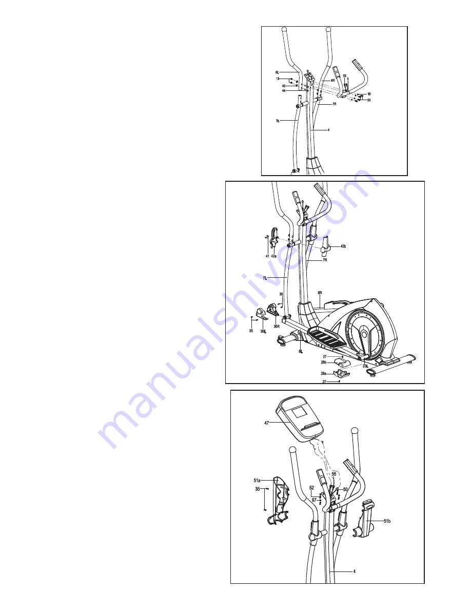
STEP 4
A: Lock the Handlebar (6L/R) onto the
Swing tube (7L/R) tightly with Carriage
bolt (44), Arc washer (43) and Nylon nut
(13).
B: Thread the Hand Pulse wire (55) into
the hole of Handlebar post (4) and then
takes it out from the computer bracket on
top as shown.
C: Lock the fixed Handlebar (5) onto the
Handlebar post (4) tightly with the Allen
bolt (53) and Spring washer (18).
STEP 5
A: Fix the Protective guard (42A/B) onto the
Swing tube (7L/R) with the Tapping Screw (41)
B: Fix the Protective guard (36L/R) onto the
connection of Swing tube (7L/R) and Pedal
support (8L/R) with the Tapping Screw (35)
C: Fix the Protective guard (28A/B) onto the
Pedal tube joint (23L/R) with the Phillips Screw
(27).
STEP 6
A: First, insert the Extension wire (50), Hand
pulse wire (55) to the hole in back of Console
(47) properly, then fix the Console (47) on the
bracket of the Handlebar post (4) with Phillips
Screw (52) and Flat washer (97)
B: Lock the Protective guard (51A/B) on the
Handlebar post (4) with the Tapping Screw (35)
as shown
C: Insert the Adapter (54) into bike and con-
nect with DC line (99).
99


