background image

32

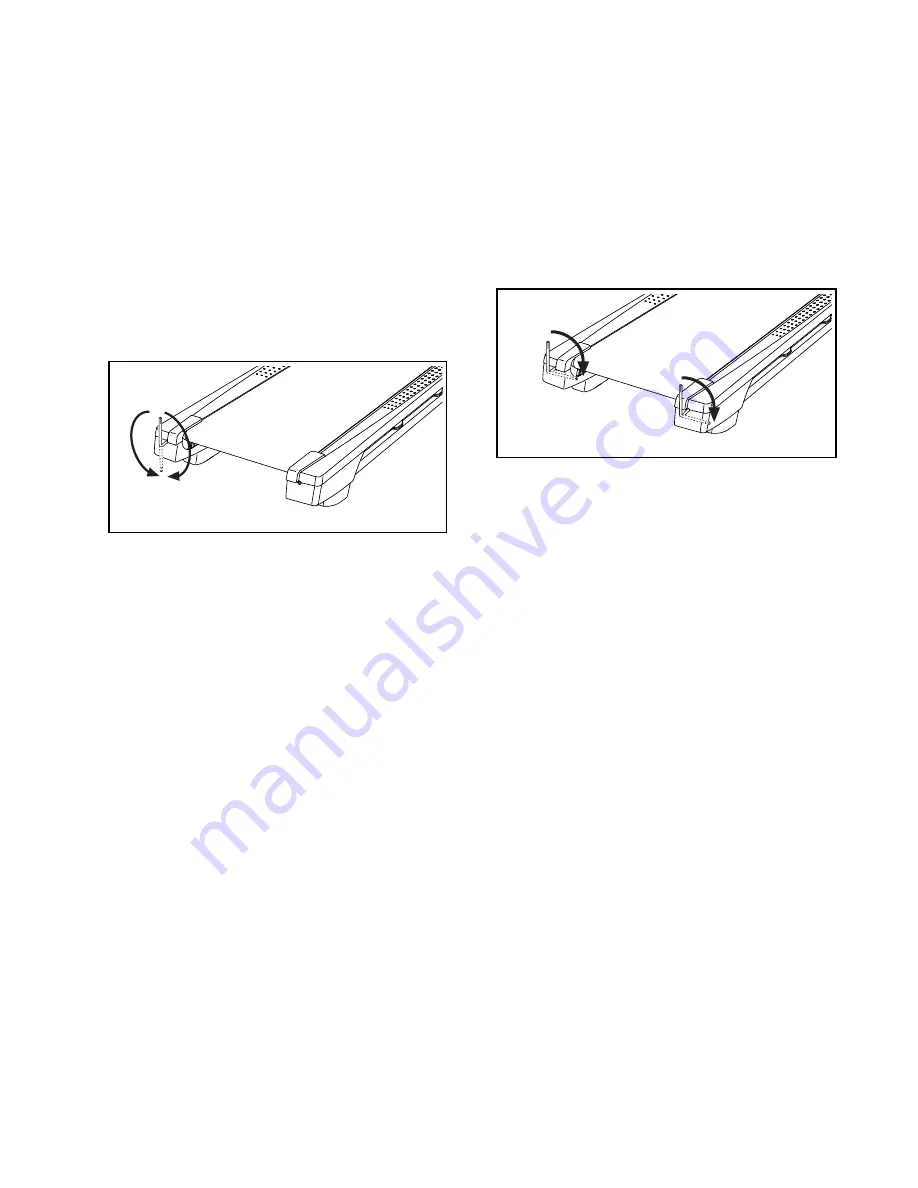
SYMPTOM: The walking belt is not centered 

between the foot rails

IMPORTANT: If the walking belt rubs against the 

foot rails, the walking belt may become damaged.

a. 


First, remove the key and 

UNPLUG THE POWER 

CORD.


If the walking belt has shifted to the left,


use the hex key to turn the left idler roller screw 

clockwise 1/2 of a turn; 

if the walking belt has 

shifted to the right,

 turn the left idler roller screw 

counterclockwise 1/2 of a turn. Be careful not to 

overtighten the walking belt.


Then, plug in the 

power cord, insert the key, and run the treadmill 

for a few minutes. Repeat until the walking belt is 

centered. 

SYMPTOM: The walking belt slips when walked on

a. 


First, remove the key and 

UNPLUG THE POWER 

CORD.

 Using the hex key, turn both idler roller 

screws clockwise, 1/4 of a turn. When the walk-

ing belt is correctly tightened, you should be able 

to lift each edge of the walking belt 2 to 3 in. (5 to 

7 cm) off the walking platform. Be careful to keep 

the walking belt centered. Then, plug in the power 

cord, insert the key, and carefully walk on the tread-

mill for a few minutes. Repeat until the walking belt 

is properly tightened.

SYMPTOM: The console display has lines running 

through it

a.   If lines appear in the console display, see THE 

SETTINGS MODE on page 27 and adjust the con-

trast level of the display.

a

a

Summary of Contents for T 13.5

Page 1: ...al for future reference www iconeurope com USER S MANUAL CUSTOMER SERVICE UNITED KINGDOM Call 08457 089 009 From Ireland 053 92 36102 Website www iconsupport eu E mail csuk iconeurope com Write ICON Health Fitness Ltd c o HI Group PLC Express Way CASTLEFORD WF10 5QJ UNITED KINGDOM AUSTRALIA Call 1800 993 770 E mail australiacc iconfitness com Write ICON Health Fitness PO Box 635 WINSTON HILLS NSW ...

Page 2: ...LIST 34 EXPLODED DRAWING 36 ORDERING REPLACEMENT PARTS Back Cover RECYCLING INFORMATION Back Cover NORDICTRACK is a registered trademark of ICON IP Inc This drawing shows the locations of the warning decals If a decal is missing or illegible call the telephone number on the front cover of this manual and request a free replacement decal Apply the decal in the location shown Note The decals may not...

Page 3: ...er appliance should be on the same circuit When replacing the fuse in the power cord adapter insert an ASTA approved BS1362 13 amp fuse into the fuse carrier 13 If an extension cord is needed use only a 3 conductor 14 gauge 1 mm2 cord that is no longer than 5 ft 1 5 m 14 Keep the power cord away from heated surfaces 15 Never move the walking belt while the power is turned off Do not operate the tr...

Page 4: ...y opening on the treadmill 25 Inspect and properly tighten all parts of the treadmill regularly 26 DANGER Always unplug the power cord immediately after use before clean ing the treadmill and before performing the maintenance and adjustment procedures described in this manual Never remove the motor hood unless instructed to do so by an authorized service representative Servicing other than the pro...

Page 5: ...dmill If you have questions after reading this manual please see the front cover of this manual To help us assist you please note the product model number and serial number before contacting us The model number and the location of the serial num ber decal are shown on the front cover of this manual Before reading further please review the drawing below and familiarize yourself with the labeled par...

Page 6: ...he key number is the quantity used for assembly Note If a part is not in the hardware kit check to see whether it is preattached Extra parts may be included 1 4 Star Washer 32 4 8 x 3 4 Screw 2 18 3 8 Star Washer 13 6 5 16 Nut 12 2 5 16 Star Washer 11 10 10 x 3 4 Screw 9 4 3 8 x 4 Screw 7 6 8 x 1 2 Silver Screw 10 1 8 x 1 2 Screw 1 8 5 16 x 1 3 4 Bolt 6 1 5 16 x 2 1 4 Bolt 3 1 10 Star Washer 5 4 5...

Page 7: ...er Left parts are marked L or Left and right parts are marked R or Right To identify small parts see page 6 Assembly requires the following tools the included hex key one adjustable wrench one Phillips screwdriver To avoid damaging parts do not use power tools 1 Go to www iconsupport eu on your computer and register your product activates your warranty saves you time if you ever need to contact Cu...

Page 8: ...awing Tie the wire tie in the Right Upright 90 securely around the end of the Upright Wire 81 Then insert the Upright Wire into the lower end of the Right Upright as you pull the other end of the wire tie out of the Right Upright 3 Lay the Right Upright 90 near the Base 94 Press the Grommet 77 into the square hole in the Right Upright Make sure not to pinch the ground wire Then attach the ground w...

Page 9: ...terial B under the right side of the Base 94 Hold the Right Upright 90 against the Base Make sure not to pinch the Upright Wire 81 Insert two 3 8 x 4 Screws 7 with two 3 8 Star Washers 13 into the Right Upright 90 and partially tighten the three Screws into the Base 94 Do not fully tighten the Screws yet Move the packing material B to the left side of the Base 94 and attach the Left Upright not sh...

Page 10: ...89 90 89 104 90 7 6 Remove and save the four indicated 5 16 x 3 4 Screws 4 Identify the Left and Right Base Covers 82 83 Slide the Left Base Cover onto the Left Upright 89 and slide the Right Base Cover onto the Right Upright 90 Do not press the Base Covers into place yet 82 90 83 6 89 4 4 ...

Page 11: ...28 11 86 C C 81 9 Position the Pulse Crossbar 93 with the pulse wire D on the left side as shown Start four 10 x 3 4 Screws 9 with four 10 Star Washers 5 into the Pulse Crossbar and the Handrails 86 Next insert the pulse wire D through the looped Cable Tie 99 on the left Handrail 86 Next slide the Pulse Crossbar 93 as far as possible in the direction shown and tighten the 10 x 3 4 Screws 9 Do not ...

Page 12: ... D as shown and insert the pulse wire into the gap indicated by the arrow Console Assembly 86 D 99 11 10 Set the console assembly face down on a soft surface to avoid scratching the console assembly Attach the Right and Left Trays 27 36 with eight 8 x 1 2 Screws 1 Do not overtighten the Screws Then remove and save the four indicated 1 4 x 1 2 Screws 31 Console Assembly 1 10 31 31 1 1 1 27 36 99 ...

Page 13: ... as shown and insert the Upright Wire into the gap indicated by the arrow Console Assembly 99 99 81 12 86 13 Set the console assembly on the brackets on the Handrails 86 Be careful not to pinch any wires Attach the console assembly with the four 1 4 x 1 2 Screws 31 that you removed in step 10 and four 1 4 Star Washers 32 Start all four Screws and then tighten them 13 86 86 31 32 Console Assembly 3...

Page 14: ...d the speaker wires H have 2 pins See the inset drawing The connectors should slide together easily and snap into place If they do not turn one connector and try again IF YOU DO NOT CONNECT THE CON NECTORS PROPERLY THE CONSOLE MAY BECOME DAMAGED WHEN YOU TURN ON THE POWER After all of the wires are connected pull the wires tight and tighten the five Cable Ties 99 around the wires Make sure that no...

Page 15: ... assembly I Also the speaker wires H need to fit into the slots in the Console Base Back Tighten ten 8 x 3 4 Screws 2 into the Console Base Back 104 in the indicated locations 2 16 104 2 2 2 2 104 Side View Flange H Slot I Slot 17 Carefully slide the Upright Crossbar 41 between the Uprights 89 90 Attach the Upright Crossbar with the four 5 16 x 3 4 Screws 4 that you removed in step 6 and four 5 16...

Page 16: ... the Latch Crossbar 38 Orient the Latch Crossbar 38 as shown Make sure that the This side toward belt sticker J is facing away from you Attach the Latch Crossbar to the brackets on the Frame 56 with the two 5 16 x 3 4 Screws 4 and two 5 16 Star Washers 11 56 38 J 11 11 4 4 Brackets 19 18 Attach the Console Cover 105 with two 8 x 3 4 Screws 2 Tighten the six 3 8 x 4 Screws 7 Then press the Base Cov...

Page 17: ...of the Storage Latch 53 to the bracket on the Base 94 with a 5 16 x 1 3 4 Bolt 6 and a 5 16 Nut 12 Raise the Storage Latch 53 to a vertical posi tion Then remove and discard the tie K 38 94 53 6 3 Decal 12 56 12 53 20 21 22 Make sure that all parts are properly tightened before you use the treadmill If there are sheets of plastic on the treadmill decals remove the plastic To protect the floor or c...

Page 18: ...atures above 122 F 50 C or below 14 F 10 C Do not excessively bend or stretch the sensor when using or storing the heart rate monitor To clean the sensor use a damp cloth and a small amount of mild soap Then wipe the sensor with a damp cloth and thoroughly dry it with a soft towel Never use alcohol abrasives or chemicals to clean the sensor Hand wash and air dry the chest strap TROUBLESHOOTING If ...

Page 19: ... power cord into the socket on the treadmill 2 Plug the power cord into an appropriate outlet that is properly installed and earthed in accordance with all local codes and ordinances DANGER Improper connection of the equipment earthing conductor can result in an increased risk of electric shock Check with a qualified electrician or serviceman if you are in doubt as to whether the product is proper...

Page 20: ...e against other iFit users and access many other features To purchase an iFit module at any time go to www iFit com or call the telephone number on the front cover of this manual You can even listen to your favorite workout music or audio books with the console s sound system while you exercise To turn on the power see page 21 To use the man ual mode see page 21 To use an onboard workout see page ...

Page 21: ... not pulled from the console adjust the posi tion of the clip HOW TO USE THE MANUAL MODE 1 Insert the key into the console See HOW TO TURN ON THE POWER at the left 2 Select the manual mode If the manual mode is not selected press the Manual Control button on the console 3 Start the walking belt To start the walking belt press the Start button the Speed increase button or one of the Speed but tons ...

Page 22: ...ned per hour As you exercise the workout intensity level bar will indicate the approximate intensity level of your exercise Press the Home button to return to the default menu see THE SETTINGS MODE on page 27 to set the default menu If necessary press the Home button again When an iFit module is con nected the wireless symbol at the top of the display will show the strength of your wireless signal...

Page 23: ... the workout In addition a profile of the speed settings of the workout will appear in the matrix If you select a calorie workout the approximate num ber of calories you will burn will appear in the name of the workout 3 Start the workout Press the Start button or the Speed increase button to start the workout A moment after you press the button the treadmill will automatically adjust to the first...

Page 24: ... step 6 on page 22 6 Turn on the fan if desired See step 7 on page 23 7 When you are finished exercising remove the key from the console See step 8 on page 23 HOW TO USE A SET A GOAL WORKOUT 1 Insert the key into the console See HOW TO TURN ON THE POWER on page 21 2 Select a set a goal workout To select a set a goal workout press the Set A Goal button on the console Use the increase and decrease b...

Page 25: ... user If more than one user is registered you can switch users in the iFit main screen Press the increase and decrease buttons next to the Enter button to select a user 4 Select an iFit workout To select an iFit workout press one of the iFit but tons Before some workouts will download you must add them to your schedule on www iFit com Press the iFit button to download the next workout in your sche...

Page 26: ...ll show how much of the race you have completed The other lines will show your top four competitors The end of the matrix represents the end of the race 7 Measure your heart rate if desired See step 6 on page 22 8 Turn on the fan if desired See step 7 on page 23 9 When you are finished exercising remove the key from the console See step 8 on page 23 For more information about the iFit mode go to w...

Page 27: ...ly when you plug in the power cord press the power switch into the reset position and insert the key into the console However when you remove the key the displays will remain lit although the buttons will not function If the demo mode is turned on the word ON will appear in the matrix To turn on or turn off the demo mode press the Enter button CONTRAST LVL Press the Incline increase and decrease b...

Page 28: ... storage position see HOW TO FOLD THE TREADMILL on page 29 For more firmness turn a cushion to the position shown in drawing 1 for less firmness turn the cushion to the position shown in drawing 2 Adjust the other cushions in the same way Note Make sure that the cushions on the left and right sides of the treadmill are set to the same firmness level The faster you run on the treadmill or the more ...

Page 29: ...treadmill Keep the treadmill out of direct sunlight Do not leave the treadmill in the storage position in temperatures above 85 F 30 C HOW TO MOVE THE TREADMILL Before moving the treadmill fold it as described at the left CAUTION Make sure that the storage latch is locked in the storage position Moving the treadmill may require two people 1 Hold the handrails with both hands and care fully push th...

Page 30: ...l frame near the power cord If the switch protrudes as shown the switch has tripped To reset the power switch wait for five minutes and then press the switch back in SYMPTOM The power turns off during use a Check the power switch see drawing c at the left If the switch has tripped wait for five minutes and then press the switch back in b Make sure that the power cord is plugged in If the power cor...

Page 31: ...ve the key from the console SYMPTOM The walking belt slows when walked on a If an extension cord is needed use only a 3 con ductor 14 gauge 1 mm2 cord that is no longer than 5 ft 1 5 m b If the walking belt is overtightened treadmill per formance may decrease and the walking belt may become damaged Remove the key and UNPLUG THE POWER CORD Using the hex key turn both idler roller screws countercloc...

Page 32: ... for a few minutes Repeat until the walking belt is centered SYMPTOM The walking belt slips when walked on a First remove the key and UNPLUG THE POWER CORD Using the hex key turn both idler roller screws clockwise 1 4 of a turn When the walk ing belt is correctly tightened you should be able to lift each edge of the walking belt 2 to 3 in 5 to 7 cm off the walking platform Be careful to keep the w...

Page 33: ...ic Exercise If your goal is to strengthen your cardiovascular system you must perform aerobic exercise which is activity that requires large amounts of oxygen for prolonged periods of time For aerobic exercise adjust the intensity of your exercise until your heart rate is near the highest number in your training zone WORKOUT GUIDELINES Warming Up Start with 5 to 10 minutes of stretch ing and light...

Page 34: ... Decal 44 1 Walking Platform 45 1 Walking Belt 46 2 Belt Guide 47 1 Right Rear Foot 48 4 Cable Tie 49 1 Drive Roller Pulley 50 1 Magnet 51 1 Reed Switch Clip 52 1 Reed Switch 53 1 Storage Latch 54 1 Drive Motor 55 1 Motor Belt 56 1 Frame 57 1 Left Rear Foot 58 1 Console Ground Wire 59 4 Rubber Cushion 60 1 Right Foot Rail 61 1 Idler Roller 62 2 Front Wheel 63 2 Wheel Spacer 64 1 Console Base 65 1 ...

Page 35: ... the back cover of this manual These parts are not illustrated 101 1 Receptacle 102 2 Console Clamp 103 1 Right Speaker Cover 104 1 Console Base Back 105 1 Console Cover 106 2 8 x 5 8 Screw 107 2 Speaker 108 1 Heart Rate Monitor 109 2 Incline Motor Spacer 110 8 6 x 1 2 Screw 111 6 3 x 3 8 Screw 112 2 Motor Bushing 113 1 Filter 114 1 Motor Plate User s Manual ...

Page 36: ... 34 30 59 61 30 34 59 23 43 44 21 100 100 46 19 19 46 8 26 39 8 26 39 1 1 4 11 4 11 34 30 59 8 26 1 39 37 8 26 1 39 8 26 1 39 8 26 1 39 2 57 2 40 40 47 2 2 37 37 37 37 37 37 38 50 35 35 35 35 35 35 10 2 10 73 10 24 10 10 113 20 112 114 EXPLODED DRAWING A Model No NETL12814 1 R0314A ...

Page 37: ...37 66 68 75 65 72 78 67 67 33 29 69 33 70 16 71 33 33 71 109 2 2 2 68 68 68 68 2 2 2 2 2 2 2 76 101 77 EXPLODED DRAWING B Model No NETL12814 1 R0314A ...

Page 38: ... 94 22 22 10 82 91 97 83 89 90 95 97 91 7 13 63 62 74 7 13 74 62 63 81 5 9 93 2 2 2 2 5 9 31 28 86 85 79 32 11 2 2 2 31 2 86 92 32 2 2 84 28 11 11 4 41 4 11 4 11 11 4 2 99 98 EXPLODED DRAWING C Model No NETL12814 1 R0314A ...

Page 39: ...102 18 58 10 80 2 64 104 27 1 1 1 1 36 1 1 1 1 87 2 88 110 107 96 107 2 111 111 2 99 2 2 2 2 103 25 2 2 2 2 2 2 2 99 106 108 110 110 110 110 110 111 111 105 2 2 2 2 EXPLODED DRAWING D Model No NETL12814 1 R0314A ...

Page 40: ...u require more information about safe and correct disposal methods please contact your local city office or the establishment where you purchased this product RECYCLING INFORMATION To order replacement parts please see the front cover of this manual To help us assist you be prepared to provide the following information when contacting us the model number and serial number of the product see the fr...

Reviews: