background image

35

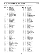
Key No. Qty.

Description

Key No. Qty.

Description

103

1

Key/Clip

104

9

Isolator Screw/Bracket Screw

105

1

Console

106

1

Idler Pulley Nut

107

1

Idler Pulley Washer

108

2

Static Decal

109

2

3/8" x 2" Bolts

110

4

5/16" Star Washer

111

4

Cushion Stop

112

1

TV Cable

113

2

TV Cable Nut

114

1

A/V Wire

115

1

Hood Cover

116

2

A/V Wire Screw

117

1

Controller Ground Wire

118

5

1/4" Flat Washer

*

12" Blue Wire, 2F

*

8" Blue Wire, M/F

*

4" Red Wire, M/F

*

User's Manual

*These parts are not illustrated. 
Specifications are subject to change without notice.

Summary of Contents for ViewPoint 3500

Page 1: ...hrider com new products prizes fitness tips and much more Visit our website at www nordictrack com new products prizes fitness tips and much more QUESTIONS As a manufacturer we are com mitted to providing complete cus tomer satisfaction If you have questions or if parts are missing PLEASE DO NOT CONTACT THE STORE please contact Customer Care IMPORTANT You must note the product model number and ser...

Page 2: ...RDERING REPLACEMENT PARTS Back Cover LIMITED WARRANTY Back Cover NordicTrack is a registered trademark of ICON IP Inc 2 The warning decals shown here have been applied in the locations shown If a decal is missing or il legible call the telephone number on the front cover of this manual and request a free replace ment decal Apply the decal in the location shown Note The decals may not be shown at a...

Page 3: ...an extension cord 12 Use only a single outlet surge suppressor that meets all of the specifications described on page 14 To purchase a surge suppressor see your local NordicTrack dealer or call the tele phone number on the front cover of this man ual and order part number 146148 or see your local electronics store 13 Failure to use a properly functioning surge suppressor could result in damage to ...

Page 4: ... procedures described in this manual Never remove the motor hood un less instructed to do so by an authorized ser vice representative Servicing other than the procedures in this manual should be performed by an authorized service representative only 26 This treadmill is intended for in home use only Do not use this treadmill in a commer cial rental or institutional setting 27 To reduce the risk of...

Page 5: ...5 SAVE THESE INSTRUCTIONS Power Lines Ground Clamps 75 Ohm Terminal Service Entrance Equipment Power Service Grounding Electrode System e g Interior Metal Water Pipe Service Entrance Conductors ...

Page 6: ...e using the treadmill If you have questions after read ing this manual please see the front cover of this man ual To help us assist you note the product model number and serial number before contacting us The model number and the location of the serial number decal are shown on the front cover of this manual Before reading further please look at the drawing below and familiarize yourself with the ...

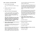
Page 7: ...been preassembled If a part is not in the parts bag check to see if it has been preassembled To avoid damaging plastic parts do not use power tools for assembly Extra hardware may be included 7 1 Make sure that the power cord is unplugged With the help of a second person carefully tip the treadmill onto its side as shown Partially fold the Frame 55 so that the treadmill is more stable Do not fully...

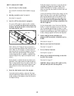
Page 8: ...the treadmill is completely assembled Insert the other Extension Leg 97 into the indi cated bracket on the base of the Uprights 85 Attach the Extension Leg 97 with two Extension Leg Bolts 87 two 5 16 Star Washers 110 and two Extension Leg Nuts 91 as shown Firmly tighten the Extension Leg Bolts 87 110 85 91 97 55 3 4 Attach two Base Pads 81 to the base of the Uprights 85 in the indicated locations ...

Page 9: ...acket Lower the Frame 55 see HOW TO LOWER THE TREADMILL FOR USE on page 28 76 20 20 Large Barrel 85 109 55 6 109 50 7 Identify the Left Base Cover 88 which has cutouts in the locations shown Slide the Left Base Cover onto the left Upright 85 Then slide the Right Base Cover 86 onto the right Upright Identify the Left Upright Sleeve 77 and the Right Upright Sleeve 9 Slide the Upright Sleeves onto th...

Page 10: ...85 and the right Upright not shown Make sure that no wires are pinched 70 Bracket 112 85 Console Assembly 9 8 Remove the band securing the Upright Wire Harness 73 to the right Upright 85 Have a second person hold the console assembly near the right Upright Connect the Upright Wire Harness 73 to the wire harness on the console assembly See the inset drawing The connectors should slide together easi...

Page 11: ... the floor or car pet from damage place a mat under the treadmill 63 7 88 86 63 7 85 12 13 Note the location of the 75 ohm terminal on the treadmill For the television to operate an audio video wire must be connected to the audio video input jack on the back of the con sole a personal audio video player must be con nected to the audio video plug on the console or a CATV cable must be connected to ...

Page 12: ...s shown and is facing away from the Console Attach the receiver to the Console in the location shown with the two included Small Screws B 3 Make sure that no wires are pinched See drawing 1 Reattach the Console 105 to the Console Base 98 with the 8 x 3 4 Screws 7 Discard the other wires included with the re ceiver If you purchase the optional chest pulse sensor see page 26 follow the steps below t...

Page 13: ... cord of your DVD player or VCR See your DVD player or VCR user s manual for proper grounding instructions 3 Connect the audio video wire to the audio video input jack on the back of the console HOW TO CONNECT A PERSONAL AUDIO VIDEO PLAYER DIRECTLY TO THE CONSOLE Locate the audio video plug below the television on the console and plug it into a jack on your MP3 player CD player or other personal a...

Page 14: ...c tion or break down grounding provides a path of least resistance for electric current to reduce the risk of elec tric shock This product is equipped with a cord having an equipment grounding conductor and a grounding plug Plug the power cord into a surge suppressor and plug the surge suppressor into an appropriate outlet that is properly installed and grounded in accordance with all local codes ...

Page 15: ...s you through every step of your workout One iFIT card with three new pro grams is included Additional iFIT cards are available separately To purchase iFIT cards at any time go to www iFIT com or call the telephone number on the front cover of this manual iFIT Cards are also available at select stores Whether you select the manual mode or a program you can enjoy the shows of your choice on the per...

Page 16: ...hange user settings press the User button again while the words USER 1 or USER 2 ap pear the words ODOMETER and TOTAL ODOMETER will appear on the screen for a few seconds The top number is the number of miles or kilometers that the user has walked or run since the number was reset To reset the number press the decrease button beside the User button The bottom number is the total number of miles or...

Page 17: ...n be turned off while you watch the television Press the Display button repeatedly to select the desired display mode To reset the console press the Stop button re move the key and then reinsert the key 7 Measure your heart rate if desired Note If you use the handgrip pulse sensor and the optional chest pulse sensor at the same time the display will not show your heart rate accurately See page 26 ...

Page 18: ...gment of the workout The height of the flashing segment indicates the speed setting for the current segment At the end of each segment a series of tones will sound and the new speed setting new incline setting and the next segment of the profile will flash in the display The workout will continue in this way until the last segment of the profile flashes in the right display and the last segment en...

Page 19: ...he User button to change the target heart rate setting see EXER CISE INTENSITY on page 32 If pulse program 2 3 or 4 is selected the maxi mum target heart rate setting of the program will appear on the screen If desired press the in crease and decrease buttons beside the User but ton to change the maximum target heart rate set ting see EXERCISE INTENSITY on page 32 Note If you change the maximum ta...

Page 20: ...of the program profile The walking belt will then slow to a stop If the speed settings and or incline settings are too high or too low you can change the intensity level of the program at any time by pressing the in crease and decrease buttons beside the User but ton to change the target heart rate setting or the maximum target heart rate setting To stop the program at any time press the Stop butt...

Page 21: ...ing can be programmed for each segment To program a speed setting and an incline setting for the first segment simply adjust the speed and in cline of the treadmill as desired by pressing the Speed and Incline buttons When the first segment of the program ends a se ries of tones will sound and the current speed set ting and the current incline setting will be saved in memory Program a speed settin...

Page 22: ...ne in cline setting are programmed for each segment Note The same speed setting and or incline set ting may be programmed for two or more consec utive segments The custom program will function in the same way as a preset program see step 4 on page 18 If desired you can redesign the program while using it To change the speed setting or the in cline setting for the current segment simply press the S...

Page 23: ...peed and incline settings of the program Hold the handrails and begin walking During the program the voice of a personal trainer will guide you through the workout Note If the AUDIO TRAINER OFF setting is selected see step 1 on page 25 the personal trainer s voice will not be heard If the speed settings and or incline settings are too high or too low you can override the settings by pressing the S...

Page 24: ...box or your VCR When the television is turned on the screen will show the last channel that was selected To select a different channel press the Channel CH but tons The selected channel number will appear on the screen for a few seconds Note The television is equipped with a channel memorizing function that allows you to go directly from the current channel to the next channel saved in memory Befo...

Page 25: ...you plug in the power cord switch the reset off circuit breaker to the reset position and insert the key into the con sole However when you remove the key the dis plays will remain lit although the buttons will not function If the demo mode is turned on the words DEMO ON will appear in the center of the display while the information mode is selected To turn on or turn off the demo mode press the S...

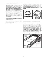
Page 26: ...ile the television is scanning channels remove the key from the console THE OPTIONAL CHEST PULSE SENSOR An optional chest pulse sensor offers hands free oper ation as it monitors your heart rate during your work outs To purchase the optional chest pulse sensor call the telephone number on the front cover of this manual HOW TO ADJUST THE CUSHIONING SYSTEM Remove the key from the console and unplug ...

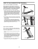
Page 27: ... Make sure that the latch knob is locked in the storage position To protect the floor or carpet from damage place a mat under the treadmill Keep the treadmill out of di rect sunlight Do not leave the treadmill in the storage position in temperatures above 85 F 30 C HOW TO MOVE THE TREADMILL Before moving the treadmill convert it to the storage posi tion as described above Make sure that the latch ...

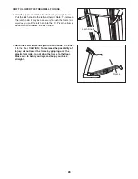
Page 28: ...h the frame for ward as you pull the latch knob to the left Pivot the frame downward and release the latch knob 2 Hold the metal frame firmly with both hands and lower it to the floor CAUTION To decrease the possibility of injury do not lower the frame by gripping only the plastic foot rails Do not drop the frame to the floor Make sure to bend your legs and keep your back straight Frame Latch Knob...

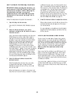
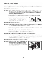
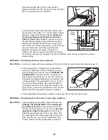
Page 29: ...ck the reset off circuit breaker see the drawing above If the circuit breaker has tripped wait for five minutes and then press the switch to the reset position b Make sure that the power cord is plugged in If the power cord is plugged in unplug it wait for five minutes and then plug it back in c Remove the key from the console Reinsert the key into the console d If the treadmill still will not run...

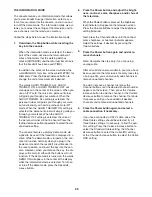
Page 30: ...y decrease and the walking belt may be come damaged Remove the key and UNPLUG THE POWER CORD Using the hex key turn both rear roller bolts counterclockwise 1 4 of a turn When the walking belt is properly tightened you should be able to lift each edge of the walking belt 3 to 4 in 8 to 10 cm off the walking platform Be careful to keep the walking belt centered Then plug in the power cord insert the...

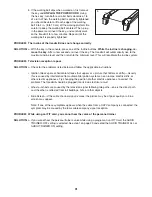
Page 31: ...ed below and follow the applicable instructions Ignition black spots or horizontal streaks that appear or a picture that flutters or drifts Usually this is caused by interference from automobile ignition systems neon lamps electric drifts or other electric appliances Try changing the position of other electric appliances to correct the problem The treadmill should be plugged into its own electrica...

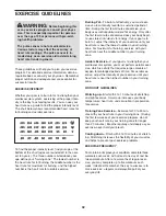
Page 32: ... goal is to strengthen your cardiovascular system you must perform aerobic exer cise which is activity that requires large amounts of oxygen for prolonged periods of time For aerobic ex ercise adjust the intensity of your exercise until your heart rate is near the highest number in your training zone WORKOUT GUIDELINES Warming up Start with 5 to 10 minutes of stretching and light exercise A warm u...

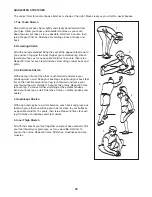
Page 33: ...illes Stretch With one leg in front of the other reach forward and place your hands against a wall Keep your back leg straight and your back foot flat on the floor Bend your front leg lean forward and move your hips toward the wall Hold for 15 counts then relax Repeat 3 times for each leg To cause further stretching of the achilles tendons bend your back leg as well Stretches Calves achilles tendo...

Page 34: ...rew 43 1 Controller 44 1 Reset Off Circuit Breaker 45 1 Belly Pan 46 1 15 1 2 Wire Tie 47 1 Power Cord 48 1 Incline Wire Harness 49 1 Hex Key 50 1 Latch Knob 51 3 Releasable Tie 52 8 Plastic Tie 53 1 Latch Endcap 54 1 Right Foot Rail 55 1 Frame 56 1 Front Roller Ground Wire 57 2 Platform Nut 58 1 Idler Washer 59 1 Idler Pulley 60 2 Rear Roller Lock Washer 61 2 Rear Roller Bracket 62 2 Rear Roller ...

Page 35: ...108 2 Static Decal 109 2 3 8 x 2 Bolts 110 4 5 16 Star Washer 111 4 Cushion Stop 112 1 TV Cable 113 2 TV Cable Nut 114 1 A V Wire 115 1 Hood Cover 116 2 A V Wire Screw 117 1 Controller Ground Wire 118 5 1 4 Flat Washer 12 Blue Wire 2F 8 Blue Wire M F 4 Red Wire M F User s Manual These parts are not illustrated Specifications are subject to change without notice ...

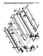
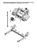
Page 36: ... 17 14 10 13 12 49 62 57 57 64 23 56 104 104 28 6 27 39 29 39 27 3 61 61 104 1 2 2 2 104 54 2 2 2 3 2 2 60 102 60 102 76 109 20 109 20 4 8 101 8 8 8 4 8 101 8 8 8 111 111 111 111 50 53 101 101 EXPLODED DRAWING A Model No NTL13007 0 R1107A 36 ...

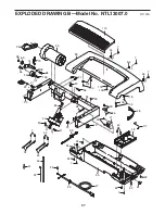
Page 37: ... 34 23 71 38 20 19 37 40 41 32 45 42 43 51 52 23 47 94 48 99 96 23 24 21 22 58 69 74 75 20 59 66 107 106 68 35 44 20 32 7 32 32 32 42 7 32 7 104 104 104 115 118 118 118 118 83 23 46 24 117 EXPLODED DRAWING B Model No NTL13007 0 R1107A ...

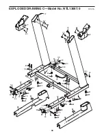
Page 38: ...82 81 82 30 80 72 67 97 87 87 91 80 81 82 30 110 97 91 73 67 88 86 84 92 20 20 92 63 7 63 7 7 9 82 82 77 72 89 65 65 89 65 65 81 82 79 81 82 79 110 112 67 112 113 101 108 38 EXPLODED DRAWING C Model No NTL13007 0 R1107A ...

Page 39: ...100 103 98 105 78 70 90 78 95 7 7 7 7 7 7 7 7 7 7 7 90 7 7 7 7 93 90 116 114 108 39 EXPLODED DRAWING D Model No NTL13007 0 R1107A ...

Page 40: ...r indirect special or consequential damages arising out of or in con nection with the use or performance of the product or damages with respect to any economic loss loss of property loss of revenues or profits loss of enjoyment or use costs of removal or installation or other consequential damages of whatsoever nature Some states do not allow the exclusion or limitation of in cidental or consequen...

Reviews: