background image

1.1 Ensure the installation complies with the installation minimum dimensions (defined below) and 
      meets the minimum and maximum connecting piping length and maximum change in elevation 
      as defined in the System Requirements section.
1.2 Air inlet and outlet will be clear of obstructions, ensuring proper airflow throughout the room.
1.3 Condensate can be easily and safely drained.
1.4 All connections can be easily made to outdoor unit.
1.5 Indoor unit is out of reach of children.
1.6 A mounting wall strong enough to withstand four times the full weight and vibration of the unit.
1.7 Filter can be easily accessed for cleaning.
1.8 Leave enough free space to allow access for routine maintenance.
1.9 Install at least 10 ft. (3 m) away from the antenna of TV set or radio. Operation of the air 
      conditioner may interfere with radio or TV reception in areas where reception is weak. An 
      amplifier may be required for the affected device.
1.10 Do not install in a laundry room or by a swimming pool due to the corrosive environment. 

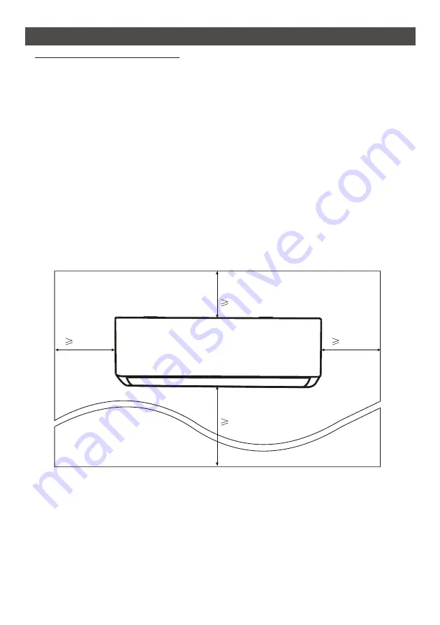
Minimum Indoor Clearances

Step1: Select Installation location

22

Floor

Ceiling

13cm

13cm

250cm

20cm

INDOOR UNIT INSTALLATION

Summary of Contents for 18K-36K

Page 1: ......

Page 2: ...sult in the escape of dangerous UV C radiation UV C radiation may even in small doses cause harm to the eyes and skin Appliances that are obviously damaged must not be operated Dot try to replace the UV C lamp Before opening the panel bearing the ultraviolet radiation hazard symbol for the conducting user maintenance it is recommended to disconnect the power Do not operate UV C lamps outside of th...

Page 3: ...PERATION MAINTENANCE TROUBLESHOOTING INSTRUCTION FOR SERVICING R32 30 27 22 4 1 19 31 14 33 13 6 The design and specifications are subject to change without prior notice for product improvement Consult with the sales agency or manufacturer for details The shape and position of buttons and indicators may vary according to the model but their function are the same ...

Page 4: ...tance of less than 50 cm from inflammable substances alcohol etc Or from pressurized containers e g spray cans 12 If the appliance is used in areas without the possibility of ventilation precautions must be taken to prevent any leaks of refrigerant gas from remaining in the environment and creating a danger of fire 13 The packaging materials are recyclable and should be disposed of in the separate...

Page 5: ...gislation and insert a thermos magnetic circuit breaker 26 The batteries in remote controller must be recycled or disposed of properly Disposal of Scrap Batteries Please discard the batteries as sorted municipal waste at the accessible collection point 27 Never remain directly exposed to the flow of cold air for a long time The direct and prolonged exposition to cold air could be dangerous for you...

Page 6: ...or lack of experience and knowledge unless they have been given supervision or instruction concerning use of the appliance by a person responsible for their safety 8 Do not climb onto or place any heavy or hot objects on top of the appliance 9 Do not leave windows or doors open for long when the air conditioner is operating 10 Do not direct the airflow onto plants or animals 11 Along direct exposi...

Page 7: ...tual object Please take the latter as the standard Mounting plate Air inlet Drainage pipe Wiring cover Connection wiring Valve protective cover With the protective cover removed Liquid valve High pressure valve Gas valve Low pressure valve 4 Refrigerant connecting pipe Air deflector and flap Air outlet Air outlet NAME OF PARTS ...

Page 8: ...d position of switches and indicators may be different according to the model but their function is the same 1 2 3 Indicator for Timer temperature and Error codes Lights up during Timer operation SLEEP mode 5 1 2 3 NAME OF PARTS ...

Page 9: ... mid mid high high TURBO function Mute function Up down auto swing Temperature indicator Meaning Left right auto swing SLEEP function Timer Battery indicator Auto Mode Health function I FEEL function ECO Mode 8 heating function o C Signal indicator Gentle wind Child Lock Display ON OFF No 1 2 3 4 5 6 7 8 9 10 11 12 13 14 15 16 17 18 19 20 21 22 23 24 25 Anti mildew function Self Clean function GEN...

Page 10: ...time for timer on off TIMER To switch on off the function SLEEP SLEEP 10 To switch on off the LED display DISPLAY To stop or start horizontal louver movement or set the desired up down air flow direction 12 13 To switch on off the I FEEL function I FEEL 14 To switch on off the MUTE function MUTE Long press to activate deactivate the GEN function depending on models To stop or start horizontal louv...

Page 11: ...to the rays of the sun 4 Keep the remote control at a distance of at least 1m from the television or other electrical appliances Each time when insert the batteries in the remote controller for the first time you can set the Cooling only or Heating pump control type As soon as you insert the batteries turn off the remote controller and operate as below 1 Long press the MODE button until the icon f...

Page 12: ...cally COOL For North American market If necessary you can press ECO button 10 times within 8 seconds under heating mode to start the forced defrosting It will defrost the outdoor ice much more fast DRY MODE This function reduces the humidity of the air to make the room more comfortable DRY To set the DRY mode Press MODE until appears in the display An automatic function of pre setting is activated...

Page 13: ...deflectors to swing from left to right the will appear on the remote display 1 3 Do it again to stop the swing movement at the current angle 2 If the vertical deflectors are positioned manually which placed under the flaps they allow to move the air flow direct to rightward or leftward TURBO function TURBO To activate turbo function press the TURBO button and will appear on the display Press again...

Page 14: ...vate 2 hours later I FEEL DISPLAY function Indoor display DISPLAY Switch ON OFF the LED display on panel Press DISPLAY button to switch off the LED display on the panel Press again to switch on the LED display ECO In this mode the appliance automatically sets the operation to save energy Press the ECO button the appears on the display and the appliance will run in ECO mode Press again to cancel it...

Page 15: ...irst press HEALTH to active this function will appear on the display Do it again to deactivate it 2 When the HEALTH function is initiated the Ionizer Plasma Bipolar Ionizer UVC Lights depending on models will be energized and running 8 heating function Optional o C 1 Long press ECO button over 3 seconds to active this function and will appear on the remote display Do it again to deactivate this fu...

Page 16: ...unit frosted the air conditioner will enable the automatic defrosting function to improve the heating effect During defrosting the indoor and outdoor fans stop running The air conditioner will resume heating automatically after defrosting finish Emergency button Open the panel and find the emergency button on the electronic control box when the remote controller fails Always press the emergency bu...

Page 17: ...example an operating gas appliance and ignition sources for example an operating electric heater 12 The appliance shall be stored so as to prevent mechanical damage from occurring 13 It is appropriate that anyone who is called upon to work on a refrigerant circuit should hold a valid and up to date certificate from an assessment authority accredited by the industry and recognizing their competence...

Page 18: ...sociated parts appropriate fire extinguishing equipment shall be available to hand Have a dry powder or CO2 fire extinguisher adjacent to the charging area 6 No ignition sources No person carrying out work in relation to a refrigeration system which involves exposing any pipe work shall use any sources of ignition in such a manner that it may lead to the risk of fire or explosion All possible igni...

Page 19: ...rth bonding 17 Repairs to sealed components 1 During repairs to sealed components all electrical supplies shall be disconnected from the equipment being worked upon prior to any removal of sealed covers etc If it is absolutely necessary to have an electrical supply to equipment during servicing then a permanently operating form of leak detection shall be located at the most critical point to warn ...

Page 20: ...ee nitrogen OFN shall then be purged through the system both before and during the brazing process 22 Removal and evacuation When breaking into the refrigerant circuit to make repairs or for any other purpose conventional procedures shall be used However it is important that best practice is followed since inflammability is a consideration The following procedure shall be adhered to Remove refrige...

Page 21: ...re that only appropriate refrigerant recovery cylinders are employed Ensure that the correct number of cylinders for holding the total system charge are available All cylinders to be used are designated for the recovered refrigerant and labeled for that refrigerant i e Special cylinders for the recovery of refrigerant Cylinders shall be complete with pressure relief valve and associated shut off v...

Page 22: ...s Prohibited Ventilation Necessary 2 Operation Safety Mind Static Electricity The maximum charge and the required minimum floor area Installation Safety Principles 3 3 3 m 4 m x LFL m 26 m x LFL m 130 m x LFL 1 2 3 3 3 Where LFL is the lower flammable limit in kg m R32 LFL is 0 038 kg m For the appliances with a charge amount m M m 1 2 The maximum charge in a room shall be in accordance with the f...

Page 23: ...frigerant leak during the installation it is necessary to immediately turn off the valve of the outdoor unit and all the personnel should go out till the refrigerant leaks completely for 15 minutes If the product is damaged it is a must to carry such damaged product back to the maintenance station and it is prohibited to weld the refrigerant pipe or conduct other operations on the user s site 6 It...

Page 24: ...R22 R410A R32 15m 5m 15g m 15m 5m 30g m R22 R410A R32 15m 5m 25g m Torque Parameters PIPE Size 1 4 6 35 3 8 9 52 1 2 12 5 8 15 88 Newton meter N x m 18 20 30 35 45 50 60 65 Pound force foot 1bf ft Kilogram force meter kgf m 24 4 27 1 40 6 47 4 61 0 67 7 81 3 88 1 2 4 2 7 4 1 4 8 6 2 6 9 8 2 8 9 Maximum Operating Current of Air Conditioner A Specification of Socket or Switch A 2 5 6 0 1 5 4 0 16 25...

Page 25: ...ildren 1 6 A mounting wall strong enough to withstand four times the full weight and vibration of the unit 1 7 Filter can be easily accessed for cleaning 1 8 Leave enough free space to allow access for routine maintenance 1 9 Install at least 10 ft 3 m away from the antenna of TV set or radio Operation of the air conditioner may interfere with radio or TV reception in areas where reception is weak...

Page 26: ...ert expansion rubber plugs into the holes then hang the mounting plate and fix it with screws A hole in the wall should be drilled for refrigerant piping the drainage pipe and connecting cables 3 1 Determine the location of wall hole base on the position of mounting plate 3 2 The hole should be have a 70mm diameter at least and a small oblique angle to facilitate drainage 3 3 Drill the wall hole w...

Page 27: ...necting pipes with the port facing up as shown in the figure NO YES 4 3 Take off the plastic cover in the pipe ports and take off the protective cover on the end of piping connectors 4 4 Check whether there is any sundry on the port of the connecting pipe and make ensure the port is clean 4 5 After align the center rotate the nut of the connecting pipe to tighten the nut as tightly as possible by ...

Page 28: ...onnect Wiring 6 1 Choose the right cables size determined by the maximum operating current on the nameplate Check the cables size refer to section INSTALLATION PRECAUTIONS 6 2 Open the front panel of indoor unit 6 3 Use a screwdriver open the electric control box cover to reveal the terminal block 6 4 Unscrew the cable clamp 6 5 Insert one end of the cable into the position of control box from the...

Page 29: ... let the snaps onto the hooks of the mounting plate and make sure it is hooked firmly Sometimes if the refrigerant pips were already embedded in the wall or if you want to connecting the pips and wires on the wall do as below I Gab both ends of the bottom plate apply a little outward force to take off the bottom plate II Hook the top of the indoor unit on the mounting plate without piping and wiri...

Page 30: ...NSTALLATION Over 200cm Over 30cm Over 50cm Over 30cm Over 50cm Install 4 rubber blankets Optional 2 1 This step only for heating pump models 2 2 Insert the drainage joint to the hole at the bottom of the outdoor unit 2 3 Connect the drainage hose to the joint and make the connection well enough 3 1 According to the The outdoor unit can be fixed on a wall mounting bracket Follow the instruction of ...

Page 31: ... as possible by hand 5 5 Use a spanner hold the body of the valve and use a torque wrench to tighten the flare nut according to the torque values in the torque requirements table Refer to the torque requirements table on section INSTALLATION PRECAUTIONS Take off the plastic cover in the pipe ports and c 4 1 Use a phillips screwdriver to unscrew wiring cover grasp and press it down gently to take i...

Page 32: ... less than 15 minutes or make sure the compound gauge indicates 0 1 MPa 76 cmHg 6 7 Close the low pressure valve of the manifold gauge and turn off the vacuum 6 8 Hold the pressure for 5 minutes make sure that the rebound of compound gauge pointer does not exceed 0 005 MPa 6 9 Open the low pressure valve counterclockwise for 1 4 turn with hexagonal wrench to let a little refrigerant fill in the sy...

Page 33: ... detection result is safe Leak detector method Use a professional leak detector and read the instruction of operation detect at the position where leakage may occur The duration of leak detection for each position should last for 3 minutes or more If the test result shows that there is leakage the nut should be tightened and tested again until there is no leakage After the leak detection is comple...

Page 34: ...with water Volatile liquid e g thinner or gasoline will damage the air conditioner so only use soft dry cloth or wet cloth dipped with neutral detergent to clean the air conditioner Pay attention to cleaning the filter screen regularly to avoid dust covering which will affect the filter screen effect When the operating environment is dusty the cleaning frequency should be increased appropriately A...

Page 35: ...f deflector assembly with your thumb and take it out Wipe the air duct and fan assembly with a clean and wrung wet rag Clean the removed parts with soapy water and air dry it After cleaning restore the removed parts in turn When the air conditioner is not in use for a long time do the following work Take out the batteries of the remote controller and disconnect the power supply of the air conditio...

Page 36: ...Back flow of liquid in the refrigerant circulation This occurs when the air in the room becomes very cold for example in the COOLING or DEHUMIDIFYING DRY modes This noise is made by the expansion or contraction of the front panel due to variations in temperature and does not indicate a problem Unsuitable temperature setting Obstructed air conditioner intakes and outlets Dirty air filter Fan speed ...

Page 37: ...nce contains refrigerant and other potentially hazardous materials When disposing of this appliance the law requires special collection and treatment DO NOT dispose of this product as household waste or unsorted municipal waste When disposing of this appliance you have the following options Dispose of the appliance at designated municipal electronic waste collection facility When buying a new appl...

Reviews: