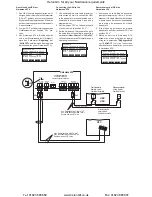
Anschluss des HSN am
Nordmann AT4
1. Den HSN über ein abgeschirmtes, zwei
-
adriges Kabel (Aderquerschnitt maximal
0.5 mm
2
) gemäss dem untenstehenden
Schema an die entsprechenden Klem men
auf dem Leistungsprint des Gerätemoduls
A anschliessen.
2. Jumper “JP3” auf dem Leistungsprint des
Gerätemoduls A auf Position “24 V” ste
-
cken.
3. Den Nordmann AT4 in Betrieb nehmen
und in der Einstellebene der Gerätesoft
-
ware den Parameter
“Regelung”
auf
“24OnOff”
einstellen (siehe Montage- und
Betriebsanleitung zum Nordmann AT4).
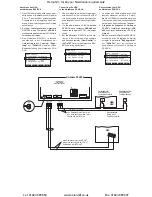
Connecting the HSN to the
Nordmann AT4
1. Use a shielded two-wire cable (maximum
wire section 0,5 mm
2
) to connect the HSN
to the appropriate terminals located on the
power board of unit module A (see wiring
diagram below).
2. Set the jumper “JP3” on the power board
of unit module A to position “24 V”.
3. Set the Nordmann AT4 into operation, go to
the setup level of the software and set the
parameter
“Hum.Control”
to
“24OnOff”
(refer to the Nordmann AT4 installation and
operating instructions).
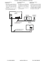
Raccordement de l’HSN au
Nordmann AT4
1. Au moyen d’un câble blindé à deux brins
(secteur maximum de l’âme: 0.5 mm
2
),
brancher l’HSN selon le schéma électrique
ci-dessous aux bornes correspondantes
de la platine de puissance du module
d’appareil A.
2. A la platine de puissance du module
d’appareil A, enficher le cavalier “JP3” sur
position “24 V”.
3. Mettre en service le Nordmann AT4,
accéder au plan de réglage du logiciel
et régler le paramètre
“Rég.hygromèt”
sur
“24OnOff”
(voir les instructions
d’installation et d’exploitation concernant
le Nordmann AT4).
Regeleinst.
Regelung :24OnOff
Sollwert :Set
Z-Begrenzung:Aus
SignalQuelle:Analog
Esc
Set
Entr.Consig.
Rég.hygromèt:24VOnOff
PointConsign:Set
An.Limiteur :Àl’arrêt
SourceSignal:Analog
Esc
Set
Controls
Hum.Control :24VOnOff
Hum.Setpoint:Set
Lim. Control:Off
SignalSource:Analog
Esc
Set
Nordmann AT4
Leistungsprint Module A
Power board Module A
Platine de puissance Module A
PE
PE
SC2
SC1
N
L1
X1
CONT. SIGN.
GND
IN
V+
X10
JP3
24V 5V
MAIN SUPPLY
MODULE B
PE
P1
N
P
X6
LIM. SIGN.
GND
IN
EXT. SUP.
5V GND 24V
X1
1
X14
GND
IN
V+
SC2
SC1
XE2
XE4
JP3
24V 5V
1
2
HBN
HSN
Sicherheitskette
Safety circuit
Chaîne de sécurité
min. Querschnitt pro Litze 1 mm
2
min. cross section per wire 1 mm
2
Section min. par fil 1 mm
2
∆p
Strömungswächter
Air flow monitor
Contôleur flux d’air
200-240 V / 50...60 Hz
max. Querschnitt pro Litze 0.5 mm
2
max. cross section per wire 0.5 mm
2
Section max. par fil 0.5 mm
2
HSC
1
2
3
Feuchtewächter
Humidity monitor
Contrôleur d'humidité
Heronhill - for all your Nordmann requirements
Tel: 01823 665660
www.heronhill.co.uk
Fax: 01823 665807


