background image

19

www.nordsonefd.com   info@nordsonefd.com

   800-556-3484    Sales and service of Nordson EFD dispensing systems are available worldwide.

Safety Enclosure for Automated Dispensing Systems

Operation

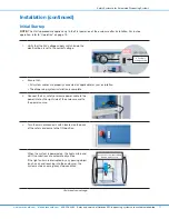
Once the robot is properly installed in the enclosure, follow these procedures for 
routine operation to ensure personnel safety.
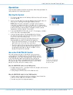
Starting the System

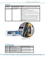
1.  Turn the main disconnect switch located on the back of the safety enclosure 

to the ON position.

2.  Refer to the robot operating manual for additional robot-specific power-on 

steps (such as switching on the DispenseMotion controller).

NOTE:

 When the system is powered on, the light curtain and all I/O 

connections are automatically active. If the light curtain is interrupted by 
any passing object (such as a hand reaching into the enclosure), the system 
enters an emergency stop condition. An emergency stop may also be 
triggered by a customer-specific I/O connection.

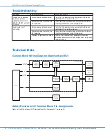
3.  Press the EMERGENCY STOP button to test it. If an emergency shutdown 

occurs, the system is operating properly.

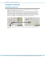
4.  Verify that the light curtain is functioning properly by moving a 

test object into the light curtain field. If an emergency shutdown 
occurs, the system is operating properly.

NOTE:

 Nordson EFD strongly recommends performing the 

following additional checks of the light curtain operation:
•  Ensure that the safety enclosure is in a location that is free of 

light interference, such as from fluorescent lamps.

•  Check the sheaths of the wiring connected to the light curtain 

controller (inside the electrical box) for damage and replace 
any damaged wiring. Refer to “Service” on page 21 for the 
location of the light curtain controller.

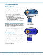
About the RUN/TEACH Switch

The safety enclosure provides a RUN/TEACH switch that affects 
system operation. The default position of the RUN/TEACH switch is 
the RUN position, which allows normal operation. Placing the switch 
in the TEACH position deactivates the light curtain, allowing the 
operator to run the robot at a reduced speed (without dispensing) or 
to service the robot. When the RUN/TEACH switch is in the TEACH 
position, the system will not run a dispense cycle.

When the RUN/TEACH switch is in the RUN position:

•  The light curtain is active — any object that passes the light curtain causes an 

emergency shutdown condition.

•  Pressing the green START button starts a dispense cycle.

When the RUN/TEACH switch is in the TEACH position:

•  The light curtain is deactivated, allowing the operator to reach inside the 

enclosure without triggering an emergency shutdown.

•  The robot cannot execute a dispense program.

Main disconnect switch

Controls on the front of the 
safety enclosure (standard 
enclosure shown)

Summary of Contents for 7362738

Page 1: ... Safety Enclosure for Automated Dispensing Systems Operating Manual Electronic pdf files of Nordson EFD manuals are also available at www nordsonefd com ...

Page 2: ...is based on more than 50 years of industrial dispensing experience Most questions you will have are answered in this manual However if you need assistance please do not hesitate to contact EFD or your authorized EFD distributor Detailed contact information is provided on the last page of this document The Nordson EFD Pledge Thank You You have just purchased the world s finest precision dispensing ...

Page 3: ...tion in the Event of a Malfunction 9 Disposal 9 Specifications 10 Operating Features 10 Installation 11 Unpack the System Components and Install the Feet 11 Vision Systems Only Install the Monitor and Keyboard 11 Install the Robot in the Enclosure 12 Connect Cables 14 Install the Dispensing System and Reinstall the Panels 15 Connect Inputs Outputs Optional 16 Initial Startup 17 Operation 19 Starti...

Page 4: ...e with EU Machinery Directive 2006 42 EC essential for all production requirements Nordson EFD safety enclosures easily integrate into existing production lines Each enclosure features an internal lockable electrical control box and integrated wireways that allow easy cable routing for faster safer setup A safety light curtain at the front opening stops the dispensing cycle anytime an object passe...

Page 5: ... SHOCK Risk of electric shock Disconnect power before removing covers and or disconnect lock out and tag switches before servicing electrical equipment If you receive even a slight electrical shock shut down all equipment immediately Do not restart the equipment until the problem has been identified and corrected MAXIMUM AIR PRESSURE Unless otherwise noted in the product manual the maximum air inp...

Page 6: ...usting or servicing high pressure equipment A jet of high pressure fluid can cut like a knife and cause serious bodily injury amputation or death Fluids penetrating the skin can also cause toxic poisoning Any injury caused by high pressure liquid can be serious If you are injured or even suspect an injury Go to an emergency room immediately Tell the doctor that you suspect an injection injury Show...

Page 7: ...operate or service equipment unless you are qualified Do not operate equipment unless safety guards doors and covers are intact and automatic interlocks are operating properly Do not bypass or disarm any safety devices Keep clear of moving equipment Before adjusting or servicing moving equipment shut off the power supply and wait until the equipment comes to a complete stop Lock out power and secu...

Page 8: ...isconnect switch first to prevent sparking Know where emergency stop buttons shutoff valves and fire extinguishers are located Preventive Maintenance As part of maintaining continuous trouble free use of this product Nordson EFD recommends the following simple preventive maintenance checks Periodically inspect tube to fitting connections for proper fit Secure as necessary Check tubing for cracks a...

Page 9: ...to local regulations after one time use Do not clean components with strong solvents MEK acetone THF etc Clean cartridge retainer systems and barrel loaders with mild detergents only To prevent fluid waste use Nordson EFD SmoothFlow pistons Action in the Event of a Malfunction If a system or any equipment in a system malfunctions shut off the system immediately and perform the following steps 1 Di...

Page 10: ...res EMERGENCY STOP and START buttons same functionality as the controls on the front of the robot Mounting base for the articulating arm with monitor stand and the keyboard tray for vision guided systems Keys for the lockable electrical box located on the back of the enclosure On the back of the enclosure Main disconnect switch designed for lockout tagout and lockable electrical box includes I O t...

Page 11: ...our M4 x 12 screws to install the monitor Unpack the System Components and Install the Feet 1 Remove loose items from inside the enclosure feet articulating arm keyboard tray and loose hardware 2 Carefully remove the enclosure and stand it upright 3 Use a pallet jack to lift a corner of the enclosure and then use an adjustable open end wrench to install the feet Repeat to install the remaining fee...

Page 12: ...four 4 vibration isolators from the enclosure 3 a Use a 5 mm hex key to remove the right side clear panel 9 screws and the two back clear panels 6 screws each b Set the panels and screws aside in a safe location Right side panel removal Back panel removal 4 Moving the robot requires a minimum of two people Do not attempt to lift the robot without assistance WARNING Avoid tilting the robot and neve...

Page 13: ...stalled Hand tighten 6 Moving the robot requires a minimum of two people Do not attempt to lift the robot without assistance WARNING Position the robot inside the safety enclosure aligning the feet to the correct holes for your robot model NOTE The safety enclosure bottom provides holes for the multiple robot sizes 7 Open the enclosure doors and use an open end wrench to install the M5 nuts remove...

Page 14: ...able to the Power Inlet 3 Connect the input output safety plug cable to the Ext Control port 4 Connect the input output I O cable to the IO Port 5 Vision systems only Connect the monitor power and DispenseMotion controller cables to the robot Teach Pendant systems only Connect the Teach Pendant to the Teach Pendant port on the front of the robot NOTES Cables can be routed through the grommet holes...

Page 15: ...ation is ideal for a dispense valve controller Power strip on top of enclosure 2 Reinstall the back clear panels and the right side clear panel using the screws removed previously 3 a Open the electrical box on the back of the safety enclosure b Set the 24V voltage supply switch to the correct setting for your installation AC supply voltage switch The automated dispensing system is now fully insta...

Page 16: ...rt pin assignments Robot I O Port Pin Assignments Pin Assignment Pin Assignment Pin 1 Input 1 Pin 14 Output 1 Pin 2 Input 2 Pin 15 Output 2 Pin 3 Input 3 Pin 16 Output 3 Pin 4 Input 4 Pin 17 Output 4 Pin 5 Input 5 Pin 18 Output 5 Pin 6 Input 6 Pin 19 Output 6 Pin 7 Input 7 Pin 20 Output 7 Pin 8 Input 8 Pin 21 Output 8 Pin 9 N C Pin 22 N C Pin 10 N C Pin 23 N C Pin 11 Ground Pin 24 24 VDC Pin 12 Gr...

Page 17: ...at All system cables are properly connected as applicable for your installation The dispensing system installation is complete 3 Connect the 5 m safety enclosure power cable to the power inlet on the right side of the enclosure and to the power source 4 Turn the main disconnect switch located on the back of the safety enclosure to the ON position When the system is powered on the light curtain and...

Page 18: ... output 8 on the I O terminal block When the output 8 signal exceeds 24V goes high the system breaks the circuit between EMG IN and EMG OUT When output 8 is high and the light curtain is broken the Emergency Stop signal locks and the robot enters a hard lock state When Output 8 is low and the light curtain is broken the Emergency Stop signal is not triggered meaning the robot is in a soft lock sta...

Page 19: ...commends performing the following additional checks of the light curtain operation Ensure that the safety enclosure is in a location that is free of light interference such as from fluorescent lamps Check the sheaths of the wiring connected to the light curtain controller inside the electrical box for damage and replace any damaged wiring Refer to Service on page 21 for the location of the light c...

Page 20: ...ispense cycle While a dispense program is running press the START button a second time to pause the dispense cycle Press a the START button a third time to resume a paused dispense cycle Stopping the System Emergency Stop An emergency stop condition occurs when the user presses the EMERGENCY STOP button on the front of the safety enclosure or when the light curtain field is broken When an emergenc...

Page 21: ...ty enclosure installation has not been changed or damaged The safety relay inside the electrical box is free from oil or dust accumulation that could interfere with conductivity The wiring connections to the safety relay inside the electrical box are secure with no loose or damaged wires NOTE Refer to the manufacturer s product manuals for additional information on light curtain and safety relay m...

Page 22: ...r cord is connected to the back right side of the safety enclosure Main disconnect switch in the OFF position Ensure that the main disconnect switch on the back of safety enclosure is in the ON position Problem in light curtain system Refer to the manufacturer s product manuals for additional information on light curtain and safety relay troubleshooting Technical Data General Block Wiring Diagram ...

Page 23: ...23 www nordsonefd com info nordsonefd com 800 556 3484 Sales and service of Nordson EFD dispensing systems are available worldwide Safety Enclosure for Automated Dispensing Systems Notes ...

Page 24: ...of purchase to be free from defects in material and workmanship but not against damage caused by misuse abrasion corrosion negligence accident faulty installation or by dispensing material incompatible with equipment when the equipment is installed and operated in accordance with factory recommendations and instructions Nordson EFD will repair or replace free of charge any part of the equipment th...

Reviews: