background image

Installation

3-8

E

1996 Nordson Corporation

All rights reserved

107 041A

Issued 1/96

Manual 12-28

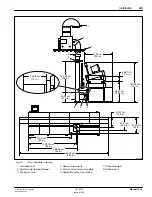
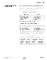
An ideal exhaust duct configuration for each oven consists of a single
203 mm (8-in.) diameter duct rising from the floor to the exhaust blower
mounted on the outside of the roof.  However, the exhaust ducts from two
or more ovens can intersect at a common point.

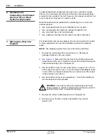
Read these exhaust duct guidelines for intersecting two or more oven
exhaust systems:

S

Use an exhaust blower for each individual oven or system

S

Use a rectangular duct leading to outside through the roof

S

Use of junction box is not recommended

S

Use a slide type damper for each drop to a system component

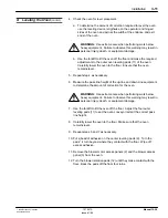
For transportation and set-up purposes, the oven is mounted on a pallet.
To move and position the oven for installation, perform the following
tasks:

NOTE:  The shipping weight of the oven is 544.32 Kg (1200 lbs).

1. Remove the shrink wrap from around the oven.  Remove all

packages shipped on the oven pallet.

2.

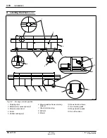
See Figure 3-2

.  Make sure that the front of the forklift is facing the

operator side of the oven.  Position the forks of the forklift through the
sheet metal openings (6) on the pallet (4).

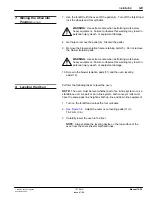
3. Use the forklift to move the oven into position.  Leave 91.47 cm (3 ft)

of floor space around the oven.  For in-line system installations, leave
10 mm (0.40 in.) of space between the oven entrance and the output
of the previous in-line device.

4. Use the forklift to lift the oven and pallet (4).  Turn off the forklift and

lock the wheels and fork cylinders.

WARNING:  Use extreme care when performing work below
heavy equipment.  Failure to observe this warning may result in
personal injury, death, or equipment damage.

5. Remove the bolts (7) attaching the oven to the pallet (4).

6. Set the oven on the floor.  Position the forklift to the oven lift

position (13).

6. Guidelines for

Intersecting the Exhaust
Ducts of Two or More
System Components

7. Moving the Oven into

Position

Summary of Contents for 107 041A

Page 1: ...Select Cure 100 Inch IR Oven Part 107 041A NORDSON CORPORATION D AMHERST OHIO D USA ...

Page 2: ...nguage without the prior written consent of Nordson Corporation The information contained in this publication is subject to change without notice Trademarks 100 Plus Blue Box ChromaFlex CleanSleeve CleanSpray Control Coat Cross Cut Easy Coat Econo Coat Flow Sentry Isocoil Isocore Iso Flo Nordson the Nordson logo PRX Pro Flo RBX Ready Coat Rhino Select Coat Select Cure Shur Lok Smart Spray System S...

Page 3: ...of a System or Component Malfunction 1 7 9 Maintenance and Repair 1 8 10 Material and Solvent Precautions 1 9 11 Disposal 1 12 1 Introduction 2 1 2 Oven Features 2 2 3 System Components 2 4 Conveyor 2 4 Process Cavity 2 4 Monitor Assembly 2 4 Oven Controller 2 4 Touchscreen Card 1 2 5 Video Card 2 2 5 Central Processing Unit CPU Card 3 2 5 Input Output I O Card 4 2 5 Silicon Control Rectifier SCR ...

Page 4: ...lower Model 3 6 Converting Air Velocity into a Volume Flow Rate 3 7 6 Guidelines for Intersecting the Exhaust Ducts of Two or More System Components 3 8 7 Moving the Oven into Position 3 8 8 Leveling the Oven 3 9 9 Installing the Alarm Light Stacks 3 12 10 Installing the Monitor Assembly 3 13 11 Making Oven Connections 3 15 12 Verifying Operating Voltages and Blower Rotation 3 16 13 Measuring and ...

Page 5: ... Up Verification Menu 4 14 7 Entering the Conformal Coating Menu 4 14 8 Daily Operation 4 14 9 Programming a Profile 4 15 Setting Up the Oven Conveyor 4 15 Setting Oven Temperature 4 16 Setting Wattage Ratios 4 17 Saving a Profile in the Oven Library 4 17 Applying a Name to a Saved Profile 4 18 10 Thermocouple Testing 4 18 11 Programming Auto Start Ups 4 19 12 Production History 4 20 13 Other Sele...

Page 6: ...y Problems 6 4 Conveyor Speed Control Problems 6 6 Conveyor Width Control Problems 6 10 Input Output Problems 6 15 Zone Problems 6 22 Thermocouple Problems 6 26 3 Open Loop Control 6 27 Changing to Open Loop Control 6 28 Configuring the CPU Card for Open Loop Control 6 29 Configuring the CPU Card for Closed Loop Control 6 30 4 Wiring Diagrams 6 31 5 Controller Card Settings and Diagrams 6 38 CPU C...

Page 7: ...eserved 107 041A Issued 1 96 Manual 12 28 1 Physical 8 1 Dimensions 8 1 Weight 8 1 2 Operating Capacities 8 2 Electrical 8 2 Pneumatic 8 2 Exhaust 8 2 Processing Area 8 2 Conveyor 8 2 Infrared Emitters 8 2 3 Curing Application Recommendations 8 3 Specifications ...

Page 8: ...Table of Contents vi E 1996 Nordson Corporation All rights reserved 107 041A Issued 1 96 Manual 12 28 ...

Page 9: ...E 1995 Nordson Corporation All rights reserved Issued 11 95 12 28s1 Section 1 Safety ...

Page 10: ...Safety 1 0 E 1995 Nordson Corporation All rights reserved Issued 11 95 12 28s1 ...

Page 11: ...ecific tasks and working with specific equipment S store this manual within easy reach of personnel installing operating maintaining or repairing this equipment S follow all applicable safety procedures required by your company industry standards and government or other regulatory agencies Refer to the National Fire Protection Association NFPA standard 33 and to federal state regulatory agency and...

Page 12: ...ing prohibited WARNING Wear protective clothing safety goggles and approved respiratory protection Failure to observe may result in serious injury WARNING Hot Risk of burns Wear heat protective clothing safety goggles with side shields and or heat protective gloves depending on the symbol shown WARNING System or material pressurized Relieve pressure Failure to observe this warning may result in se...

Page 13: ...quipment damage Use this equipment only as described in this manual Nordson Corporation cannot be responsible for injuries or damages resulting from nonstandard unintended applications of its equipment This equipment is designed and intended only for the purpose described in this manual Uses not described in this manual are considered unintended uses and may result in serious personal injury death...

Page 14: ...f valves in the air supply lines to the system This allows you to relieve air pressure and lock out the pneumatic system before undertaking maintenance and repairs S Install a locking disconnect switch or breaker in the service line ahead of any electrical equipment S Use only electrical wire of sufficient gauge and insulation to handle the rated current demand All wiring must meet local codes S G...

Page 15: ... check them for proper functioning Only qualified personnel physically capable of operating the equipment and with no impairments to their judgement or reaction times should operate this equipment Read all system component manuals before operating this equipment A thorough understanding of system components and their operation will help you operate the system safely and efficiently S Before starti...

Page 16: ...ctive equipment objects being sprayed and fluid containers are connected to a true earth ground S Never touch exposed electrical connections on equipment while the power is ON S If you notice electrical arcing in the spray area shut down the system immediately An arc can cause a fire or explosion S Do not operate the equipment at pressures higher than the rated maximum working pressure of any comp...

Page 17: ...he equipment Operators should also be aware of less obvious dangers in the workplace that often cannot be completely eliminated S exposed surfaces on the equipment which may be hot or have sharp edges and cannot be practically safeguarded S vapors and materials such as coatings which may cause allergic reactions or other health problems S automatic hydraulic pneumatic equipment or mechanical parts...

Page 18: ...pment may void agency approvals and create safety hazards S Refer to the MSDS before using solvents to clean this equipment The MSDS will provide use storage and disposal information about the solvent Read this information carefully and follow instructions WARNING Note the flash point of the cleaning solvent used Only use controlled methods and equipment such as temperature controlled or explosion...

Page 19: ...wer as soon as the test is over S Do not attempt to service electrical equipment if there is standing water present Do not service electrical equipment in a high humidity environment S Use tools with insulated handles when working with electrical equipment S Keep high voltage connection points clean and insulated with dielectric grease or oil S Do not attempt to service a moving piece of equipment...

Page 20: ...cards are supplied with the equipment Additional cards are available free from Nordson Corporation WARNING Injection hazard Do not go near a known leak in a hose or fitting and stay clear of all dispensing gun nozzles or orifices Do not point a film coater at yourself or other personnel The high pressure fluid stream can penetrate skin and inject fluid into the body causing serious injury or death...

Page 21: ...plier to determine whether your existing materials and solvents contain halogenated hydrocarbons or to obtain a suitable nonhalogenated hydrocarbon solvent for cleaning and flushing your system S See Table 1 1 Check the labels on your solvent containers Halogenated hydrocarbon solvents can be recognized if any of the following elements are listed in the name of the product or or as an ingredient E...

Page 22: ...alogenated Fluids Chlorinated Solvents Iodinated Solvents Brominated Solvents Fluorocarbon Solvents Carbon Tetrachloride Ethyl Iodide Ethylene Dibromide Dichlorofluoromethane Chloroform Methyl Iodide Methyl Bromide Trichlorofluoromethane Ethylene Dichloride N butyl Iodide Methylene Chlorobromide Freon Methylene Chloride Propyl Iodide 1 1 1 Trichloroethane Monochlorobenzene Orthodichlorobenzene Per...

Page 23: ...E 1996 Nordson Corporation All rights reserved 107 041A Issued 1 96 Manual 12 28 Section 2 Description ...

Page 24: ...Description 2 0 E 1996 Nordson Corporation All rights reserved 107 041A Issued 1 96 Manual 12 28 ...

Page 25: ...nfra red IR oven is a conveyor driven system for heat curing printed circuit board PCB coatings Oven operation is simplified through the use of a touchscreen display monitor and pre loaded control system software The oven is part of the Select Coat In Line System but can be used as a standalone unit 1228007A Fig 2 1 Typical Select Cure 100 Inch IR Oven 1 Introduction ...

Page 26: ...r Adjustable to accept printed circuit board widths from 50 8 mm to 406 4 mm 2 in to 16 in ÁÁÁ ÁÁÁ 10 ÁÁÁÁÁÁÁÁ ÁÁÁÁÁÁÁÁ Hinged side ÁÁÁÁÁÁÁÁÁÁÁÁÁÁÁÁÁÁÁÁÁÁÁÁÁ ÁÁÁÁÁÁÁÁÁÁÁÁÁÁÁÁÁÁÁÁÁÁÁÁÁ Denotes the back of the oven ÁÁÁ ÁÁÁ 11 ÁÁÁÁÁÁÁÁ ÁÁÁÁÁÁÁÁ Operator side ÁÁÁÁÁÁÁÁÁÁÁÁÁÁÁÁÁÁÁÁÁÁÁÁÁ ÁÁÁÁÁÁÁÁÁÁÁÁÁÁÁÁÁÁÁÁÁÁÁÁÁ Denotes the front of the oven ÁÁÁ ÁÁÁ 12 ÁÁÁÁÁÁÁÁ ÁÁÁÁÁÁÁÁ Exit end ÁÁÁÁÁÁÁÁÁÁÁÁÁÁÁÁÁÁÁÁÁÁÁÁ...

Page 27: ...ht stack status 3 Circuit breaker 4 Monitor assembly 5 Alarm light stack stack up 6 Cooling cavity 7 Conveyor rail fixed 8 Reset switch 9 Conveyor rail movable 10 Hinged side 11 Operator side 12 Exit end 13 Process cavity 14 Storage area 15 Entrance end 16 In line equipment connector 17 Manual override cover 18 Manual override storage area door 19 Exhaust port 20 Air inlet 21 Service line entrance...

Page 28: ...p the temperature of the PCB components as low as possible The monitor assembly contains a capacitive sensitive touchscreen and VGA color monitor Users input information by touching the touchscreen pads The touchscreen pads are either active or inactive in relation to the menus displayed on the monitor The oven controller directs the operation of the oven It provides oven status parameters and ala...

Page 29: ...t also receives operating data from other cards for oven operation and user display The card features a sound generator to indicate alarm conditions and a battery back up for curing profile storage Input Output I O Card 4 This card receives inputs from the oven and sends data to the CPU card The CPU card acts on the data and responds appropriately to the system I O card inputs and the their associ...

Page 30: ...ly turns on the display monitor S Storage area door valve releases the latch on the storage area doors for 15 seconds S Alarm alerts the CPU Card to error conditions or oven failures S Alarm light stack turns on the appropriate operational status alarm light of the oven Silicon Control Rectifier SCR Card 5 and 6 This card controls the SCR s that deliver power to the IR lamps in each oven zone The ...

Page 31: ...he process cavity and circulates it throughout the oven This airflow pattern cools the PCB IR lamps and reflectors It also insulates the ovens internal temperature environment from the surrounding external ambient temperature Continuous exhausting of the oven is necessary for safe and effective operation Exhaust air exits the oven at a low volume to conserve air usage and help control curing tempe...

Page 32: ...Description 2 8 E 1996 Nordson Corporation All rights reserved 107 041A Issued 1 96 Manual 12 28 ...

Page 33: ...E 1996 Nordson Corporation All rights reserved 107 041A Issued 1 96 Manual 12 28 Section 3 Installation ...

Page 34: ...Installation 3 0 E 1996 Nordson Corporation All rights reserved 107 041A Issued 1 96 Manual 12 28 ...

Page 35: ...cal conduit electrical service line and supply air line to the oven is the sole responsibility of the customer A clean dry 0 01 cmm 0 4 cfm compressed air supply delivered at 5 5 bar 80 psi is required to raise the oven s cover Connection to the oven is through a 9 5 mm 3 8 in quick connect coupling near the oven exhaust port Always use an independent 3 phase electrical service line for the ovens ...

Page 36: ... exhaust duct and the oven exhaust should not be less than 152 4 m 6 in S An ideal exhaust duct consists of an 203 2 mm 8 in diameter duct rising from the floor to a roof mounted blower S Install a U shaped duct at the roof to prevent water from entering the oven exhaust air handling system S Adjust the pass line height for the in line system specifications S Wire the air handling exhaust blower t...

Page 37: ...54 61 cm 243 84 cm 7 4 5 6 1 2 3 96 in 21 5 in 137 9 cm 55 in 26 67 cm 10 5 in 187 96 cm 74 in 37 88 in 32 in 26 5 in 16 5 in 180 in 98 in 94 in 85 in 304 8 cm 12 in Fig 3 1 Oven installation drawing 1 U shaped duct 2 Roof mounted exhaust blower 3 Facility roof line 4 Service line conduit 5 Female quick connect coupling 6 Adjustable exhaust duct base 7 Exhaust damper 8 Exhaust duct ...

Page 38: ...gle inlet exhaust blower model from an existing manufacture S a backward incline wheel to insure non overloading at any static pressure S a belt drive for ease of repairs The exhaust blowers circuit must be wired to simultaneously turn on with the oven s blower Always install a time delay relay in the exhaust blower circuit to continue blower operation for 5 minutes after the ovens blower turns of...

Page 39: ...straight duct length LA Actual straight duct length LE Equivalent straight duct length of elbows ÁÁÁÁÁÁÁÁÁÁÁÁÁ ÁÁÁÁÁÁÁÁÁÁÁÁÁ Metric Units ÁÁÁÁÁÁÁÁÁÁ ÁÁÁÁÁÁÁÁÁÁ US Units ÁÁÁÁÁÁÁÁÁÁÁÁÁ ÁÁÁÁÁÁÁÁÁÁÁÁÁ ÁÁÁÁÁÁÁÁÁÁÁÁÁ LT 7 62 m 26 39 m LT 34 01 ÁÁÁÁÁÁÁÁÁÁ ÁÁÁÁÁÁÁÁÁÁ ÁÁÁÁÁÁÁÁÁÁ LT 25 ft 86 67 ft LT 111 67 b Calculate the estimated pressure loss for the exhaust duct NOTE From a duct loss chart in the Ameri...

Page 40: ...e rated at a static pressure of at least 14 7 mm 0 55 in of water higher than that seen at a pitot tube located at the exhaust duct center However when choosing a blower its a good idea to select one rated for a 12 7 to 25 4 mm 0 5 to 1 0 in static pressure higher than the valve calculated above Therefore for this example choose an exhaust blower capable of delivering 17 cmm 600 cfm of airflow at ...

Page 41: ...US Units ÁÁÁÁÁÁÁÁÁÁÁÁÁ ÁÁÁÁÁÁÁÁÁÁÁÁÁ ÁÁÁÁÁÁÁÁÁÁÁÁÁ 203 mm exhaust duct ÁÁÁÁÁÁÁÁÁÁ ÁÁÁÁÁÁÁÁÁÁ ÁÁÁÁÁÁÁÁÁÁ 8 in exhaust duct ÁÁÁÁÁÁÁÁÁÁÁÁÁ ÁÁÁÁÁÁÁÁÁÁÁÁÁ ÁÁÁÁÁÁÁÁÁÁÁÁÁ ÁÁÁÁÁÁÁÁÁÁÁÁÁ ÁÁÁÁÁÁÁÁÁÁÁÁÁ cmm m min 0 032 cmm 442 5 m min 0 032 cmm 14 16 ÁÁÁÁÁÁÁÁÁÁ ÁÁÁÁÁÁÁÁÁÁ ÁÁÁÁÁÁÁÁÁÁ ÁÁÁÁÁÁÁÁÁÁ ÁÁÁÁÁÁÁÁÁÁ cfm ft min 0 349 cfm 1432 66 ft min 0 349 cfm 500 cfm NOTE Table 3 1 contains selected air velocities and...

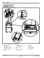
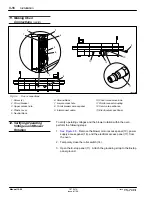
Page 42: ...is 544 32 Kg 1200 lbs 1 Remove the shrink wrap from around the oven Remove all packages shipped on the oven pallet 2 See Figure 3 2 Make sure that the front of the forklift is facing the operator side of the oven Position the forks of the forklift through the sheet metal openings 6 on the pallet 4 3 Use the forklift to move the oven into position Leave 91 47 cm 3 ft of floor space around the oven ...

Page 43: ...low heavy equipment Failure to observe this warning may result in personal injury death or equipment damage 10 Screw in the blower isolation pads 11 and the oven leveling pads 12 Perform the following tasks to level the oven NOTE The oven must be level whether part of an in line system or as a standalone unit As part of an in line system both conveyor rails must have the same pass line height as b...

Page 44: ...11 13 11 Fig 3 2 Moving oven into position 1 Shipping clips 2 Blower motor access panel 2 3 Blower access panel 4 Pallet 5 Rubber bushings 4 6 Blower isolation frame retaining bolts 4 7 Sheet metal opening 8 Bolts 6 9 Blower 10 Blower isolation frame 11 Oven leveling pads 12 Blower isolation pads 13 Oven lift position 8 Leveling the Oven contd ...

Page 45: ... necessary 6 Measure the pass line height of the up line and down line equipment to determine the amount of correction for the oven WARNING Use extreme care when performing work below heavy equipment Failure to observe this warning may result in personal injury death or equipment damage 7 Use the forklift to lift the oven off the floor Adjust the four outer leveling pads 11 to set the oven conveyo...

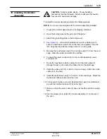
Page 46: ...ct to the oven 15 Install the blower access panel 3 and blower motor access panels 2 on the oven 16 Remove the shipping clips 1 from the oven Save the clips Install the red orange and green alarm stack at the oven entrance end and the blue alarm stack at the exit end of the oven To install the alarm stacks perform the following tasks 1 Unpack the alarm stacks from their shipping container 2 See Fi...

Page 47: ...he lock with the unlock notch 17 on the guide 5 Remove the touchscreen card 12 and video card 13 from the card cage Place the cards on a static free surface 6 Connect the power connector 4 to the monitor assembly power connector 5 7 Route the touchscreen ribbon cable 3 and the video cable 2 through the slot on the side of the fans and into the card cage 8 Install the video card 13 in slot 2 of the...

Page 48: ... stack and monitor assembly installation 1 Monitor assembly 2 Video cable 3 Touchscreen ribbon cable 4 Monitor assembly power connector 5 Oven power connector 6 Screw 4 7 Alarm stack tower 8 Alarm stack connector 9 Oven connector 10 Base 11 Hex head set screw 12 Touchscreen card 13 Video card 14 Card slot 15 Lower card guide 16 Notched card lock 17 Unlock notch 10 Installing the Monitor Assembly c...

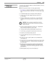
Page 49: ...to observe this caution may result in equipment damage 5 Remove all packing material from inside the oven Inspect the IR lamps for damage Replace any broken lamps 6 Turn the manual override counterclockwise to lower the cover 7 Turn off lock out and tag the 3 phase service line to the oven 8 Remove the circuit breaker access panel 8 9 Route and attach the service line conduit to the service line e...

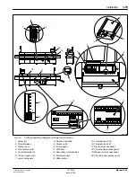
Page 50: ...over manual override 11 Quick connect coupling 12 Service line entrance 13 Electrical access Panel To verify operating voltages and the blower rotation within the oven perform the following steps 1 See Figure 3 5 Remove the blower motor access panel 19 power supply access panel 18 and the electrical access panel 17 from the oven 2 Temporary close the roller switch 14 3 Open the E stop panel 11 Att...

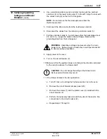
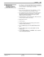
Page 51: ... WARNING Hazardous voltages are present when the main power is on Serious injury or death may result if personnel fail to observe safety procedures 8 Apply power to the oven 9 Turn on the circuit breaker 2 10 Make sure that the system blower is rotating in the direction indicated by the red arrow above the blower shaft CAUTION Do not change the wiring at the blower motor Serious system failure may...

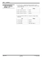
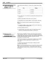
Page 52: ...R card 11 Measure the secondary voltage between these pins Pins Voltage 1 and 2 7 and 8 13 and 14 15 VAC 3 and 4 9 and 10 15 and 16 12 VAC 5 and 6 11 and 12 17 and 18 120 VAC 13 Locate terminal block TB235 16 Measure the voltage between these pins Pins Voltage 1 and 2 gnd 20 VDC 3 and 4 gnd 20 VDC 5 and 6 gnd 5 25 VDC approx 12 Verifying Operating Voltages and Blower Rotation contd ...

Page 53: ...1 6 Fig 3 5 Verifying operating voltages and blower motor rotation 1 Screw 3 2 Circuit breaker 3 Plastic cover 4 Touchscreen card 5 Controller cards 6 6 Thermocouple card 7 Lower card guide 8 Notched card lock 9 Unlock notch 10 E stop panel 11 SSR card 12 Secondary terminal block 13 Electrical panel 14 Roller switch 15 Terminal block 235 16 Terminal block 241 17 Electrical access panel 18 Power su...

Page 54: ...ical access panel 17 on the oven Measuring and controlling the air flow in the exhaust duct is critical for proper operation of the oven The procedure is simplified by taking one reading at the center of the exhaust duct This can be done automatically using an Exhaust Controller or manually using either a hot wire anemometer or a pitot tube set up The Exhaust Controller is an optional piece of equ...

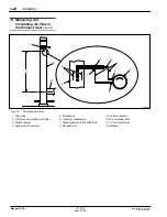
Page 55: ... total pressure outlet 2 of the pitot tube 1 Use the plastic tubing 3 to connect the manometer low side 6 to the static pressure outlet 7 of the pitot tube 1 5 Insert the pitot tube 1 into the exhaust duct 8 Make sure the end of the tube faces the direction of air flow 9 6 Apply power to the oven 7 Turn on the oven 8 Touch the reset switch on the exit end E stop panel to enter the POWER UP VERIFIC...

Page 56: ...0 Fig 3 6 Measuring air flow 1 Pitot tube 2 Total pressure outlet pitot tube 3 Plastic tubing 4 High side manometer 5 Manometer 6 Low side manometer 7 Static pressure outlet pitot tube 8 Exhaust duct 9 Air flow direction 10 Oven exhaust duct 11 7 5 duct diameters 12 Damper 13 Measuring and Controlling Air Flow in the Exhaust Duct contd ...

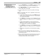
Page 57: ...ch the digit pads to enter the desire wattage value Wattage entry occurs in the highlighted area c To select the bottom IR lamps of a zone touch the top zone SETPT pad in the WATTS column of the desired zone row twice The selected bottom zone setpoint value highlights d Touch ENTER to turn the lamp off Touch the digit pads to enter the desire wattage value Wattage entry occurs in the highlighted a...

Page 58: ...the Exhaust Duct A 3 1415 r2 A area of duct in square meters feet r radius of the duct in meters feet For duct diameters of 152 4 203 2 254 and 304 8 mm For duct diameters of 6 8 10 and 12 in 152 4 203 2 254 304 8 A 0 018 A 0 032 A 0 051 A 0 073 6 8 10 12 A 0 196 A 0 349 A 0 545 A 0 785 Volume Flow Rate Q AV A Q volume of flow in cubic meters per minute cmm AV air velocity in meters per min mpm A ...

Page 59: ...UTION Before selecting product width remove all boards from the oven Failure to observe this caution will result in damage to equipment 9 Press the PRD WIDTH pad Press ENTER Follow the message prompts on the SET UP SCREEN menu and set the width of the conveyor 10 Turn off the oven circuit breaker Turn off lock out and tag the 3 phase service line to the oven 11 Open the E stop panel at the exit en...

Page 60: ...stall the CPU card in the card cage 16 Connect the cable to the CPU card Use a small screwdriver pencil or similar tool to push the notched card lock 13 to the right to lock cards in place 17 Remove the wrist strap from the E stop cover Close the cover 18 Apply power to the oven 19 Turn on the oven 20 Perform a thermocouple test Refer to the Operation section for the procedures 14 Setting the Conv...

Page 61: ...E 1996 Nordson Corporation All rights reserved 107 041A Issued 1 96 Manual 12 28 Section 4 Operation ...

Page 62: ...Operation 4 0 E 1996 Nordson Corporation All rights reserved 107 041A Issued 1 96 Manual 12 28 ...

Page 63: ... input data The following occurs when touching the monitor assembly touchscreen S a high pitched tone for an active pad S a low pitch tone for an inactive pad S highlighting and a high pitched tone for an active menu item pad S a message prompt and blinking red cursor for menu items requiring variable entries S a low pitch tone for an inactive menu item pad During oven operation the touchscreen di...

Page 64: ... 1960 ÁÁÁÁÁÁÁÁÁÁÁÁÁÁÁÁÁÁ ÁÁÁÁÁÁÁÁÁÁÁÁÁÁÁÁÁÁ ÁÁÁÁÁÁÁÁÁÁÁÁÁÁÁÁÁÁ Access the MAINTENANCE STATUS screen from the POWER VERIFICATION screen ÁÁÁÁÁÁ ÁÁÁÁÁÁ ÁÁÁÁÁÁ 5220 ÁÁÁÁÁÁÁÁÁÁÁÁÁÁÁÁÁÁ ÁÁÁÁÁÁÁÁÁÁÁÁÁÁÁÁÁÁ ÁÁÁÁÁÁÁÁÁÁÁÁÁÁÁÁÁÁ Access the SET UP screen from the CONFORMAL COATING CURING screen ÁÁÁÁÁÁ ÁÁÁÁÁÁ ÁÁÁÁÁÁ 4090 ÁÁÁÁÁÁÁÁÁÁÁÁÁÁÁÁÁÁ ÁÁÁÁÁÁÁÁÁÁÁÁÁÁÁÁÁÁ ÁÁÁÁÁÁÁÁÁÁÁÁÁÁÁÁÁÁ Return the CONFORMAL COATING CURI...

Page 65: ...FILTER CLEAN LUBRICATE CONVEYOR E STOP ACTIVATED OPERATOR SCREEN SHUTDOWN AUTO START UP PROGRAM 2288 AUTO START UP PROGRAM PROCESS LIBRARY PROCESS DATA THERMOCOUPLE TEST 45 MIN CLEAN SUPPORT RAIL LEAD SCREWS CHECK RAIL EDGE HEAT DEFLECTORS 5220 SET UP SCREEN POWER UP VERIFICATION RESET RECOVERY FROM POWER LOSS 1357 SWITCH CONFIGURATION 0825 SYSTEM SET UP EXHAUST CONTROLLER LIBRARY SCREEN EDIT SCRE...

Page 66: ...ired to operate oven 1228031A POWER UP VERIFICATION AUTO START UP STATUS CURRENT DAY TIME SUNDAY THU 09 25 MONDAY TUESDAY WEDNESDAY THURSDAY 480 3Y FRIDAY 60 Hz SATURDAY 0 1 2 3 4 5 6 7 8 9 Screen 4 1 Power Up Verification Menu This menu is used by maintenance personnel It lists required maintenance routines their performance time schedules and accumulated hours between routine performance Exiting...

Page 67: ...doors S shutdown the oven S view the current operating status 1228033A CONFORMAL COATING CURING CURING OTHER OPTIONS OPERATOR SCRN UNLOCK DOOR RAISE COVER SET UP SCRN COMMUNICATIONS SHUTDOWN LIBRARY SCRN THERMO TEST PROCESS DATA PROG AUTO START MAINTENANCE SCRN CURRENT STATUS Machine idle Process cavity not in use CLEAR ENTER 0 1 2 3 4 5 6 7 8 9 Screen 4 2 Conformal Coating Curing Menu Conformal C...

Page 68: ...d width PRD WIDTH S board length PROD LENGTH S zone ZN lamp wattage WATTS and temperature TEMP C for a saved or created profile These menus also display the S current outside temperature Ambient temperature AT S outside temperature when creating a profile Profile Temperature PT S current profile running PART S oven curing control method METHOD lamp current WATTS or thermocouple TEMP Operator and S...

Page 69: ... MENU LIBRARY WATTS TEMP C SAVE PROFILE SETPT ACTUAL SETPT ACTUAL HEAT ON ZN 1 TOP 1000 2000 210 099 ZN 1 BOT 1000 2011 064 ZN 2 T OP 1000 1332 107 105 ZN 2 BOT 1000 1336 84 METHOD TEMP ZN 3 TOP 0000 0000 070 ZN 3 BOT 0000 0000 079 ZN 4 TOP 1000 1340 190 111 ZN 4 BOT 1000 1342 086 PROGRAM ZN 5 TOP 1000 1343 250 123 ENTER ZN 5 BOT 1000 1344 95 EDGE HEAT 1 0200 0199 EDGE HEAT 2 0000 0000 CLEAR PART ...

Page 70: ...50 123 ENTER ZN 5 BOT 1000 1344 95 EDGE HEAT 1 0200 0199 EDGE HEAT 2 0000 0000 CLEAR PART 111 MESSAGE AREA 0 1 2 3 4 5 6 7 8 9 Screen 4 4 Set up Screen Menu See Screen 4 5 The library contains the created profiles for the oven Use the SET UP SCREEN Menu to create and store profiles in the library by part number For each profile the library contains S conveyor speed and pace delay CNV S board width...

Page 71: ...sers to apply a name up to 12 letters to an existing profile Use the SET UP SCREEN menu to access this menu 1228028A 125 LIBRARY SCREEN PART CNV WH LN ZN1 ZN2 ZN3 ZN4 ZN5 EDG 111 065 354 6 1247 0398 0000 0482 1110 0200 T 0100 300 0 1248 0397 0000 0481 1109 0000 B 211 172 119 193 251 T PT 27 METH T 099 129 122 122 157 B 112 060 354 6 1552 0000 0000 0337 1072 0200 0010 300 0 1553 0000 0000 0336 1071...

Page 72: ...R S T U V W X Y Z SPC EXIT 0 1 2 3 4 5 6 7 8 9 Screen 4 6 Edit Screen Menu See Screen 4 7 Use this menu to verify the oven thermocouple and exhaust levels This menu displays a count down clock and the last performance date of the test Always run the test on a cold oven after installation and every seven days thereafter The test takes 45 minutes to complete Use the START TEST and STOP TEST items to...

Page 73: ...134 95 EDGE HEAT 1 0000 AT EDGE HEAT 2 0000 25 27 PT THERMOCOUPLE TEST CYCLE NOT EXECUTING LAST TEST START TEST STOP TEST TO MENU 06 13 Screen 4 7 Thermocouple Test Cycle Menu See Screen 4 8 Use this menu to program automatic start times for a profile or a thermocouple test cycle The profile or test occurs on schedule every week as long as power remains applied to the oven Start times are based on...

Page 74: ... on the oven When running a profile sensors count PCB s as they enter and exist the oven process cavity The number of processed PCB s is contained in the LIBRARY PROCESS DATA menu See Screen 4 10 The LIBRARY PROCESS DATA menu displays the S profile part number PART S profile run time and date START TIME S profile running time ELAPSED TIME S PCB quantity PRODUCT COUNT S PCB rejection quantity REJEC...

Page 75: ...E ENTER DISPLAY BY PART NEXT PAGE Screen 4 9 Process Data Screen Menu 1228035A LIBRARY PROCESS DATA PART 100 hrs START TIME 13 26 10 14 ELAPSED TIME 00000 00 20 PRODUCT COUNT 00000 REJECT QUANTITY 00000 00 00 SYSTEM SHUTDOWN 13 26 10 14 PROCESS LIBRARY PRINT Screen 4 10Library Process Data menu Process Data Screen and Library Process Data Menu contd ...

Page 76: ...ent or technician when routine maintenance is required 2 Touch the To Menu pad to enter the CONFORMAL COATING CURING menu Perform the following steps to select and run a profile 1 Enter the CONFORMAL COATING CURING menu 2 Touch the OPERATOR SCRN pad Press ENTER to change to the OPERATOR SCREEN menu CAUTION Entering an new part number will calibrate the oven conveyor rails Before entering a new par...

Page 77: ...n may result in equipment damage 5 For standalone ovens place a PCB on the conveyor The conveyor grips the edges of the PCB 6 For in line ovens adjust the oven conveyor speed to the system s conveyor speed A profile is a trial and error process between oven through put desired curing and maximum allowable temperature NOTE Call your Nordson distributor or representative for assistance in developing...

Page 78: ...s of oven operation temperature values appear in the SET UP SCREEN menu s actual column All actual bottom zone temperatures transfer over to the set point column when the profile is saved in the library Perform the following to program the profiles zone temperature into the oven NOTE When the SETPT menu item is highlighted the message area displays the current top and bottom wattage ratio for that...

Page 79: ...ea displays the change in wattage 3 To select the bottom IR lamps of a zone touch the top zone SETPT pad in the WATTS column of the desired zone row twice The selected bottom zone setpoint value highlights 4 Touch ENTER to turn the lamp off Touch the digit pads to enter the desire wattage value or enter 0 or 1 for even lamp intensity Wattage entry occurs in the highlighted area The oven control sy...

Page 80: ...to return to the CONFORMAL COATING CURING menu Perform a thermocouple test after installation The test should be done after every seven days of PCB production This test takes approximately 45 min to complete Actual zone temperatures are within 9 O C of their setpoint temperatures for a passing test These are causes of a thermocouple test failure S faulty or blocked exhaust blower S incorrect dampe...

Page 81: ...P VERIFICATION menus To program the oven for automatic start up perform these steps 1 Enter the CONFORMAL COATING CURING menu 2 Touch the PROG AUTO START pad Touch the ENTER pad 3 Enter code 2288 to gain access to the AUTOMATIC START UP PROGRAM menu 4 Touch the desired day pad Touch the digit pads to enter a time of day for the automatic start up The oven uses a 24 hour clock format 5 For auto sta...

Page 82: ...the Library Process Data menu for the selected profile 5 Press PROCESS LIBRARY pad to return to the Process Data Screen menu 6 Repeat steps 3 through 5 to view the profiles history 7 Touch the EXIT pad to return to the CONFORMAL COATING CURING menu To raise the ovens cover shut down the oven unlock the storage area doors and get communication link information perform the following from the CONFORM...

Page 83: ...E 1996 Nordson Corporation All rights reserved 107 041A Issued 1 96 Manual 12 28 Section 5 Maintenance ...

Page 84: ...Maintenance 5 0 E 1996 Nordson Corporation All rights reserved 107 041A Issued 1 96 Manual 12 28 ...

Page 85: ...ated hours between routine performance Read the menu RUN HOURS on a daily bases to determine when to perform maintenance To perform maintenance on the oven perform the following steps NOTE Some of the routines listed on the MAINTENANCE STATUS menu require the oven to be off and cool For those routines perform the maintenance task before performing the following procedure 1 Perform the tasks necess...

Page 86: ...ES 400 hrs 0100 CHANGE AIR FILTER 400 hrs 0153 EXHAUST CONTROLLER 200 hrs 0044 CLEAN LUBRICATE CONVEYOR 400 hrs 0000 CLEAN SUPPORT RAIL LEAD SCREWS 400 hrs 0073 REPLACE RAIL EDGE HEAT REFLECTORS 4000 hrs 0933 0505 3004 PERFORM MAINTENANCE TO MENU Screen 5 1 Oven Maintenance Status Menu Before start up perform the following tasks 1 Use a clean cloth to remove any accumulation of dust or dirt CAUTIO...

Page 87: ... control and even intensity Replace the IR lamps as necessary Perform the following to verify IR lamp operation within each oven zone 1 Turn on the oven Enter the MAINTENANCE STATUS menu Select VERIFY ZONES 2 Press and hold the cover switch View the cover and base lamps for even intensity 3 Replace all malfunctioning lamps 4 Touch and hold the Maintenance Complete pad to lower the oven cover retur...

Page 88: ...ds from within the process cavity 4 See Figure 5 1 Remove both lamp grommets 11 5 Observe how the lamp connectors 9 clip onto the lamp bus 11 Disconnect the lamp connectors from the buss 6 Slide the old lamp out through the lamp grommet 11 hole Discard the lamp 7 Install the new lamp through the lamp grommet 11 hole Firmly attach the new lamp connectors 9 to the lamp buss 10 8 Replace both lamp gr...

Page 89: ... 1 96 Manual 12 28 Cover and Base Lamps contd 1228025A 11 2 3 1 4 1 3 9 10 8 7 5 6 Fig 5 1 Base and edge heat lamp replacement 1 Ceramic protector 2 Lamp lead 3 Lamp 4 Buss bar 5 Junction reflector 6 Screw 5 7 Screw 4 8 Cover plate 9 lamp connector 10 Lamp buss 11 Lamp grommet 2 ...

Page 90: ...yor Follow the message prompts on the SET UP SCREEN menu Remove all boards from within the process cavity 6 Touch the digit pads to enter a conveyor width of 50 8 mm 2 in Press ENTER 7 Touch the CONVEYOR pad Touch ENTER Follow the message prompts on the SET UP SCREEN menu 8 Disconnect system power to the oven 9 Using a flat blade screwdriver turn the manual override clockwise to raise the oven cov...

Page 91: ...veyors tension and width after the first 400 hours of oven operation then as required thereafter CAUTION Do not over lubricate the conveyor Excess oil attracts dirt resulting in increased torque on the drive motors Failure to observe this caution will result in equipment damage Nordson recommends using a light high temperature synthetic oil on the conveyor Perform the following steps to lubricate ...

Page 92: ... Repeat steps a through c for the fixed rail 4 For nose guide oiling perform the following steps a Remove the cap from the oil dispensing bottle 4 b Insert the bottle in either rail nose guide hole 5 at the oven s exit end 7 c Select the Begin lubricating chain on movable rail or Begin lubricating chain on fixed rail pad NOTE The countdown begins on the touchscreen display d When an alarm sounds t...

Page 93: ...eserved 107 041A Issued 1 96 Manual 12 28 1228014A 7 4 5 6 3 1 2 Fig 5 2 Lubricating the conveyor 1 Large sprocket 2 Idler block assembly 3 Rail cover 4 4 Oil dispensing bottle 5 Rail nose guide hole 6 Sprocket guard 7 Oven exit end Lubricate Conveyor contd ...

Page 94: ... perform the following steps NOTE Make all tension adjustments to the non spring load idler tension block located at the opposite end of the conveyor rail 1 Turn off the oven at the main disconnect Let the oven cool off 2 See Figure 5 2 Remove the sprocket guards 6 and rail covers 3 from the entrance and exit ends of the conveyor rails 3 Using two open end wrenches adjust the idler block assembly ...

Page 95: ... sprocket set screw 6 Manually set the conveyor width 1 to 50 8 mm 2 in 7 Set flags on the limit switch board halfway through their optical sensors 8 Connect the lead screws to the drive shafts Mesh the miter gears 7 and tighten set screws Calibrating the Conveyor Width Perform the following to calibrate the ovens conveyor width NOTE Do not move the rail unless all sprockets and gears are securely...

Page 96: ...trance and exit lead screws b Check for a 0 254 mm 0 01 in side to side PCB movement on the conveyor through the process cavity 8 Perform the following steps when the conveyor is out of calibration a Write down the difference between the existing rail position and the desired calibrated rail position b Turn the oven off c Loosen the miter gear set screws hinged side Manually set the rail width to ...

Page 97: ...d 107 041A Issued 1 96 Manual 12 28 Calibrating the Conveyor Width contd 1228017A 3 5 7 1 4 6 2 Fig 5 3 Conveyor adjustments 1 Conveyor width 2 Calibration box cover 3 Limit switch board 4 Sprocket 5 5 Drive chain entrance end 6 Drive chain exit end 7 Miter gear 5 ...

Page 98: ...code 5220 to gain access to the SET UP SCREEN menu CAUTION Before selecting product width remove all boards curing in the oven Failure to observe this caution will result in damage to equipment 5 Touch the PRD WIDTH pad Touch ENTER to calibrate the conveyor Follow the message prompts on the SET UP SCREEN menu Remove all boards from within the process cavity 6 Touch the digit pads to enter a convey...

Page 99: ...Install the blower motor access panels 8 and the blower access panel 9 2 Check the conveyor system for wear 3 Check the blower belts 2 for wear If necessary perform the following steps to replace the blower belts a See Figure 5 4 Turn oven off and let it cool Remove the blower motor access panel 8 b Loosen both nuts 4 and the pivot bolt 3 on the blower motor support bracket c Carefully loosen both...

Page 100: ...nels Check the conveyor speed and width motor chains for wear Replace if necessary 1228011A 1 2 3 6 7 8 9 4 5 Fig 5 4 Air filter blower bearings and blower belt 1 Bearing plugs 2 Blower belts 3 Pivot bolt 2 4 Nut 2 5 Support bolt 2 6 Air filter 7 Air filter access panel 8 Blower motor access panel 2 9 Blower access panel 8 Semiannually contd ...

Page 101: ...E 1996 Nordson Corporation All rights reserved 107 041A Issued 1 96 Manual 12 28 Section 6 Troubleshooting ...

Page 102: ...Troubleshooting 6 0 E 1996 Nordson Corporation All rights reserved 107 041A Issued 1 96 Manual 12 28 ...

Page 103: ... this caution may result in equipment damage WARNING Moving equipment Use extreme care when working with hands near moving chains and sprockets Failure to observe this warning may result in personal injury or equipment damage This section contains troubleshooting procedures These procedures cover only the most common problems that you may encounter If you cannot solve the problem with the informat...

Page 104: ...veyor rail does not change position 6 10 2 Calibrating conveyor causes movable rail to crash into the oven inner wall 6 12 3 PRD WIDTH actual value slightly overshoots setpoint 6 13 Table 6 4 Input Output Problems Problem Page 1 Input Output functions 6 15 2 No menu displayed on monitor assembly 6 16 3 Main contactor not energizing 6 17 4 Blower contactor not energizing E Stop not pressed 6 18 5 C...

Page 105: ...nts 0 6 22 3 Zone s will not turn on 6 23 4 Lack of zone control or zone circuit breaker trips 6 24 5 Zone failure with setpoints 0 6 25 6 Zone turns on but incorrect wattage present 6 25 Table 6 6 Thermocouple Problems Problem Page 1 Actual temperature display is unreasonable 6 26 2 Temperature drops while watts rise or the opposite occurs 6 26 3 Thermocouple failure screen 6 26 1 Introduction co...

Page 106: ...Verify that oven transformer s primary wiring configuration verses schematic is correct for the given 3 phase service line voltage Measure incoming 3 phase service line voltage If service line voltage is not correct S change service line to match the oven configuration S install an oven power conversion kit Call your Nordson representative for more information 3 phase service line dips and surges ...

Page 107: ... 120 VAC 3 4 9 10 15 16 12 VAC If voltages are not present turn oven off Disconnect all wires from transformer secondary terminal block Turn oven on and verify secondary voltages If voltages are not present replace 3 phase transformer If transformer secondary voltages are present turn oven off Check for wiring shorts or bad component associated with desired voltage Repair as necessary 4 Loss of 18...

Page 108: ... 2 5 cm 1 in Check for a short in wires 1099 and 1119 and power supply board Replace as necessary If no short is found turn on oven Measure for 5 25 VDC at power supply board s output If no voltage is measured replace board Bad controller card Turn oven off Install controller cards Turn oven on and measure for 5 25 VDC at the power supply board s output If voltage is present check for a short on 5...

Page 109: ...ed motor If shaft does not rotate replace speed motor Tighten set screw Reset circuit breaker CB2 Open cable 2415 See Figure 6 2 Turn off oven Check cable 2415 for an open 230PL 1 C24 to 241PL 1 pin 1 230PL 1 A24 to 241PL 1 pin 2 230PL 1 A23 to 241PL 1 pin 3 230PL 1 C23 to 241PL 1 pin 4 If an open is found repair cable Bad dual motor controller card or conveyor speed motor assembly See Figures 6 2...

Page 110: ...bly Turn on oven Verify that 18 VDC exists between A9 gnd and A8 pos on the dual motor controller card If voltage is not present replace dual motor controller card If voltage is present manually turn input shaft of conveyor speed motor Use a voltmeter to verify that a toggling voltage of 0 VDC to 5 VDC is present between A9 gnd and A7 pos on the dual motor controller card NOTE To use an oscillosco...

Page 111: ...ge Verify the settings on switches 6 7 and 8 of Bank 2 Set switches as necessary Open or shorted cable 2455 If switch settings are correct check cable 2455 for an intermittent short or open 230PL 1 pin A7 to 241PL 1 pin 8 230PL 1 pin A8 to 241PL 1 pin 6 230PL 1 pin A9 to 241PL 1pin 9 If a short or an open is found repair the cable Bad dual motor controller card If a short or open is not found in c...

Page 112: ...aker CB1 or CB2 tripped Turn oven off and check for tripped circuit breaker s Manually open oven cover and check entire length of conveyor for obstructions If circuit breaker CB2 tripped check for a short on 18 VDC line Short occurred on the 18 VDC line Check for a short on the 18 VDC line of limit switch board encoder board conveyor speed motor assembly or conveyor width motor assembly Reset brea...

Page 113: ...or controller card NOTE If limit flag activates limit switch board s optical switch before rail reaches its inner limit PRD WIDTH actual column should read calibrating If it does not replace dual motor controller card If movable rail is not at inner limit turn off oven After a few seconds turn on oven Enter RAISE COVER SCREEN menu Verify that PRD WIDTH actual column displays If actual column conta...

Page 114: ...present replace dual motor controller card Open cable 2415 or bad conveyor width assembly Measure voltage between pins A19 C19 gnd and A20 C20 on dual motor controller card If 40 VDC is not present replace dual motor controller card If voltage is present use an ohmmeter to check cable 2415 230PL 1 pin A19 to 250PL 1 pin 4 230PL 1 pin C19 to 250PL 1 pin 3 230PL 1 pin A20 to 250PL 1 pin 2 230PL 1 pi...

Page 115: ... do not turn off replace limit switch board 3 PRD WIDTH actual value slightly overshoots setpoint Bad encoder board While in RAISE COVER SCREEN menu remove gear from the encoder board shaft Mark the encoder shaft Slowly rotate encoder shaft one complete turn The actual PRD WIDTH value should changed by 5 08 mm Slowly rotate shaft back to its starting point The PRD WIDTH actual value should return ...

Page 116: ...ound repair cable 2455 Bad dual motor controller card or conveyor width motor assembly Manually turn conveyor width motor shaft Measure voltage between pins C9 gnd and C7 pos on dual motor controller card As conveyor width motor pulse wheel moves through optical switch verify that voltage toggles between 0 and 5 VDC If voltage level toggles replace dual motor controller card If voltage level does ...

Page 117: ...r the oven Problem Possible Cause Corrective Action 1 Input Output functions I O card circuit breaker CB1 tripped wiring or component shorted See Figure 6 2 Check I O circuit breaker If tripped check for a short on the I O card 18 VDC line Check for S shorts on the SSR card S supply air or exhaust pressure switch connectors shorting to oven S cover switch es connectors shorting to oven S air valve...

Page 118: ...se is good either video card or monitor is faulty Bad I O card If 120 VAC is not present verify that I O card LED 01 is on If LED 01 is off replace I O card Bad SSR card If I O card LED O1 is on verify that SSR card LED D4 labeled CRT is on If LED D4 is off replace the SSR card If LED D4 is on turn off oven Remove black dust cover from connector J8 on the SSR card Turn on oven Use a voltmeter to v...

Page 119: ...e 2053 replace SSR card Bad main contactor Use a voltmeter to check for 120 VAC between A1 and A2 on main contactor If 120 VAC is present replace main contactor Open E Stop button Cover Switch or Overtemperature CR237 Turn off oven Remove black dust cover from J8 and J7 on SSR card Turn on oven Access OPERATOR SCREEN menu Check for 120 VAC between pins 8 and 9 of connector J8 on SSR card If voltag...

Page 120: ...R LED is on Check for 120 VAC between A1 and A2 on blower contactor If 120 VAC is present check for tripped circuit breakers in blower circuit Reset breakers as necessary If circuit breaker s immediately trips turn off oven Check for a short in blower motor circuitry Replace all shorted or defective components If breakers have not tripped replace blower contactor If 120 VAC is not present turn off...

Page 121: ...d turn on oven Access the RAISE COVER menu Use a voltmeter to check for 12 VDC between SSR card connector J8 pins 17 gnd and 16 If voltage is not present replace SSR card Install connector cover on J8 6 Oven over temperature Bad I O card Verify that LED I2 on I O card is on If LED is off replace I O card Bad thermostats reset switch PB204 or wiring See Figure 6 2 If LED I2 on I O board is on press...

Page 122: ... wire as necessary Turn on oven Press reset button Verify that 18 VDC is present between these pins CR237 pins 15 gnd to pin 9 15 gnd to pin 10 If voltage is present replace relay CR237 7 Exhaust Failure Incorrect exhaust level Verify that the oven exhaust system is operating at correct level Adjust as necessary Bad I O card wiring or static pressure switch See Figure 6 2 Make sure I O card LED I3...

Page 123: ...d LED I6 is on If LED is off check for an open in wires 2200 and 2210 Repair as necessary If no open wire is found check for an open static pressure switch If an open is found replace static pressure switch SW 221 9 E Stop not detected when switch pressed Defective I O board Verify that I O card LED I7 is on If LED on turn oven off Replace I O card E Stop button or wiring defective See Figure 6 2 ...

Page 124: ...he voltage between these pins Pins Voltage 1 and 2 12 VDC 3 and 4 12 VDC 5 and 6 12 VDC 2 One or more zones turn on when setpoints 0 Shorted wires or miscellaneous problems Access the SET UP SCREEN menu Set all zone temperatures to 0 _C Verify that all zones remain off If any zone turns on turn the oven off Check for shorts in zones that turn on Repair all shorted wires or components See Figure 7 ...

Page 125: ... bad SCR cube or IR lamps Turn on oven and access the SET UP SCREEN menu Set all zone temperatures equaled to 0 _C See Figure 6 5 On bad zone s SCR power cube measure DC voltage across SCR feedback card mounting screws If 0 VDC is present replace SCR power cube If a 10 VDC voltage is present measure voltage across zone approximate VAC Zone Oven Service voltage line voltage 55 VAC 208 VAC oven 103 ...

Page 126: ...eedback card s IDC connector If voltage is present at connector perform problem 3 of Power Supply Problems If no error occurs during power up turn off oven See Figures 6 1 and 6 5 Check for opens and shorts in ribbon cables from SCR card to SCR feedback card Repair as necessary If no short or open is found in cables enter a zone wattage setpoint of 300 If zero column value is below 1000 replace th...

Page 127: ...n Verify dip switch configuration on CPU and I O boards Reset as necessary Turn on oven and enter CONFORMAL COATING CURING menu Use a true RMS meter to measure voltage and current wattage of bad zone Calculate wattage watts volts x amps of bad zone Compare calculated wattage with value displayed in actual column If calculated and actual wattage values are off by an extreme amount replace SCR feedb...

Page 128: ...od wires to the bad location If zone is good replace thermocouple card 2 Temperature drops while watts rise or the opposite occurs Thermocouple wires are installed backwards on thermocouple card Rewire thermocouple card as necessary See Figure 6 2 for proper thermocouple wiring sequence Refer to Controller Card Settings and Wiriing Diagrams for additional information 3 Thermocouple failure screen ...

Page 129: ...UAL valves for S conveyor speed CONVEYOR S board width PRD WIDTH S board length PROD LENGTH S zone ZN lamp wattage WATTS and temperature TEMP C for a saved or created profile The menu also displays the S wattage setpoint values for each zone SETPOINT S SCR zero crossing points for each zone ZERO S actual watts for each zone ACTUAL S actual temperature in degrees centigrade of each zone TEMP C ACTU...

Page 130: ...0 1694 1243 123 ENTER ZN 5 BOT 1000 1975 1344 95 EDGE HEAT 1 0200 1773 0199 EDGE HEAT 2 0000 1762 0000 CLEAR MESSAGE AREA 0 1 2 3 4 5 6 7 8 9 Screen 6 1 Open Loop Control Screen Menu For open loop control perform the following steps 1 Turn the oven off Turn the oven on 2 On the touchscreen enter code 7736 to gain access to the IR ZONE OPEN LOOP CONTROL menu If menu access denied perform Configurin...

Page 131: ...uide to the left Align the lock with the unlock notch on the front of the guide 5 Disconnect the cable from the CPU card slot 3 Pull the card out of the card gage 6 Set dip switch 1 on bank 2 to the ON position Install the CPU card in the card cage 7 Connect the cable to the CPU card Use a small screwdriver pencil or similar tool to push the notched card lock to the right to lock cards in place 8 ...

Page 132: ...Use a small screwdriver pencil or similar tool to push the notched card lock on the lower card guide to the left Align the lock with the unlock notch on the front of the guide 5 Disconnect the cable from the CPU card slot 3 Pull the card out of the card gage 6 Set dip switch 1 on bank 2 to the OFF position Install the CPU card in the card cage 7 Connect the cable to the CPU card Use a small screwd...

Page 133: ...all wiring diagram of the oven Alphabetical designators are used for off page connections between sheets of the same figure Connections between figures are designated by the three digit numbers within hexagons These three digit numbers correspond to the grid numbers at the extreme left or right of the page The four digit numbers above the wires on the diagrams are wire and cable labels within the ...

Page 134: ...2 E 1996 Nordson Corporation All rights reserved 107 041A Issued 1 96 Manual 12 28 1228001A 130 171 130 171 130 171 130 171 130 171 130 171 130 196 Fig 6 1 AC power and lamp feedback wiring diagram 4 Wiring Diagrams contd ...

Page 135: ...Troubleshooting 6 33 E 1996 Nordson Corporation All rights reserved 107 041A Issued 1 96 Manual 12 28 1228002A 130 171 130 171 130 171 130 171 130 171 130 171 130 188 ...

Page 136: ...ooting 6 34 E 1996 Nordson Corporation All rights reserved 107 041A Issued 1 96 Manual 12 28 1228003A 130 170 130 169 146 601 130 144 186 364 Fig 6 2 Card cage and interface board diagram 4 Wiring Diagrams contd ...

Page 137: ...Troubleshooting 6 35 E 1996 Nordson Corporation All rights reserved 107 041A Issued 1 96 Manual 12 28 1228004A 130 163 146 603 130 164 186 384 130 162 130 167 130 167 186 376 186 361 ...

Page 138: ...Troubleshooting 6 36 E 1996 Nordson Corporation All rights reserved 107 041A Issued 1 96 Manual 12 28 1228006A Fig 6 3 IR lamp zone wiring diagram 4 Wiring Diagrams contd ...

Page 139: ...Troubleshooting 6 37 E 1996 Nordson Corporation All rights reserved 107 041A Issued 1 96 Manual 12 28 1228005A Fig 6 4 Customer system connection wiring diagram 4 Wiring Diagrams contd ...

Page 140: ... within the oven card cage Tables 6 7 through 6 12 contain controller card dip switch jumper and indicator definitions 1228037A ROM BUSS ROM BUSS ROM BUSS ROM S2 S1 VOLUME 1 BUSS S1 CB1 INTERLOCK RESET O16 O1 I16 I1 1 2 3 4 1 1 017 018 019 Fig 6 5 Oven Controller Cards 1 Touchscreen card 2 Video card 3 CPU card 4 I O card 5 Controller Card Settings and Diagrams ...

Page 141: ...eserved 107 041A Issued 1 96 Manual 12 28 1228038A ROM BUSS ROM BUSS BUSS CB2 1 2 3 J2 J5 J3 J6 J4 J7 1 CB1 ROM 1 S1 S1 J8 J1 Fig 6 6 Oven Controller Cards 1 SCR card 2 Dual motor controller card 3 Thermocouple card 5 Controller Card Settings and Diagrams contd ...

Page 142: ...le OFF Product Support Conveyor not available ÁÁÁÁÁÁ ÁÁÁÁÁÁ ÁÁÁÁÁÁ ÁÁÁÁÁÁ 4 ÁÁÁÁÁÁÁÁÁÁÁÁÁÁÁÁÁ ÁÁÁÁÁÁÁÁÁÁÁÁÁÁÁÁÁ ÁÁÁÁÁÁÁÁÁÁÁÁÁÁÁÁÁ ÁÁÁÁÁÁÁÁÁÁÁÁÁÁÁÁÁ Bottom side cooling option only ON Top IR lamps are not product width dependent OFF Top IR lamps are product width dependent ÁÁÁÁÁÁ ÁÁÁÁÁÁ ÁÁÁÁÁÁ ÁÁÁÁÁÁ ÁÁÁÁÁÁ 5 ÁÁÁÁÁÁÁÁÁÁÁÁÁÁÁÁÁ ÁÁÁÁÁÁÁÁÁÁÁÁÁÁÁÁÁ ÁÁÁÁÁÁÁÁÁÁÁÁÁÁÁÁÁ ÁÁÁÁÁÁÁÁÁÁÁÁÁÁÁÁÁ ÁÁÁÁÁÁÁÁÁÁÁÁÁÁÁÁÁ ...

Page 143: ...ation ÁÁÁÁÁ ÁÁÁÁÁ ÁÁÁÁÁ ÁÁÁÁÁ ÁÁÁÁÁ ÁÁÁÁÁ 7 and 8 ÁÁÁÁÁÁÁÁÁÁÁÁÁÁÁÁÁÁ ÁÁÁÁÁÁÁÁÁÁÁÁÁÁÁÁÁÁ ÁÁÁÁÁÁÁÁÁÁÁÁÁÁÁÁÁÁ ÁÁÁÁÁÁÁÁÁÁÁÁÁÁÁÁÁÁ ÁÁÁÁÁÁÁÁÁÁÁÁÁÁÁÁÁÁ ÁÁÁÁÁÁÁÁÁÁÁÁÁÁÁÁÁÁ Gear ratio of the conveyor speed motor Gear Ratio S7 S8 MOTOR 254 1 OFF OFF Merkle 242 1 ON OFF Barber colman 450 2 1 OFF ON Merkle See Figure 6 3 Refer to table 6 9 for I O card dip switch definitions Refer to Table 6 10 for I10L and L...

Page 144: ...ÁÁÁÁÁÁÁÁ ÁÁÁÁÁÁÁÁÁÁÁÁÁÁÁÁÁÁ OFF conveyor jammed excessive torque sensor ÁÁÁÁÁ ÁÁÁÁÁ I10 I16 ÁÁÁÁÁÁÁÁÁÁÁÁÁÁÁÁÁÁ ÁÁÁÁÁÁÁÁÁÁÁÁÁÁÁÁÁÁ Not used ÁÁÁÁÁÁÁÁÁÁÁÁÁÁÁÁÁÁÁÁÁÁ ÁÁÁÁÁÁÁÁÁÁÁÁÁÁÁÁÁÁÁÁÁÁ ÁÁÁÁÁÁÁÁÁÁÁÁÁÁÁÁÁÁÁÁÁÁ Output O ÁÁÁÁÁ ÁÁÁÁÁ O1 ÁÁÁÁÁÁÁÁÁÁÁÁÁÁÁÁÁÁ ÁÁÁÁÁÁÁÁÁÁÁÁÁÁÁÁÁÁ OFF Monitor not on ÁÁÁÁÁ ÁÁÁÁÁ O2 ÁÁÁÁÁÁÁÁÁÁÁÁÁÁÁÁÁÁ ÁÁÁÁÁÁÁÁÁÁÁÁÁÁÁÁÁÁ ON Over cover opened raised open cover valve ÁÁÁÁÁ ÁÁÁÁÁ O...

Page 145: ...ÁÁÁÁÁÁ ÁÁÁÁÁÁÁÁÁÁÁ J6 C ÁÁÁÁÁÁÁÁÁÁÁÁ ÁÁÁÁÁÁÁÁÁÁÁÁ J7 B ÁÁÁÁÁÁÁÁÁÁÁ ÁÁÁÁÁÁÁÁÁÁÁ J7 A ÁÁÁÁÁÁÁÁÁÁÁÁ ÁÁÁÁÁÁÁÁÁÁÁÁ J8 A B ÁÁÁÁÁÁÁÁÁÁÁ ÁÁÁÁÁÁÁÁÁÁÁ J8 B C ÁÁÁÁÁÁÁÁÁÁÁÁ ÁÁÁÁÁÁÁÁÁÁÁÁ J1 1 open cut ÁÁÁÁÁÁÁÁÁÁÁ ÁÁÁÁÁÁÁÁÁÁÁ J1 1 jumper ÁÁÁÁÁÁÁÁÁÁÁÁ ÁÁÁÁÁÁÁÁÁÁÁÁ J1 2 jumper ÁÁÁÁÁÁÁÁÁÁÁ ÁÁÁÁÁÁÁÁÁÁÁ J1 2 open cut See Figure 6 4 Card circuit breakers CB1 and CB2 will trip during a conveyor run away and jammed con...

Page 146: ...1 2 4 3 5B 1 2 4 3 4B 1 2 4 3 3B 1 2 4 3 2B 1 2 4 3 5T 1 2 4 3 4T 1 2 4 3 3T 1 2 4 3 2T 1 2 4 3 1B 1 2 4 3 1T BLOWER CONTACTOR MAIN CONTACTOR 103 2AMP 104 2AMP 110 4AMP 111 4AMP 112 4AMP 113 4AMP 114 4AMP 115 4AMP 116 4AMP 118 4AMP SSR CARD T 113 3 PHASE TRANSFORMER CB119 CB118 CB117 2T 3T 4T 1T 5T 2B 3B 4B 5B E1 E2 1B CIRCUIT BREAKERS GLASS FUSES SCR CUBES AND FEEDBACK CARDS Fig 6 7 Electrical pa...

Page 147: ...E 1996 Nordson Corporation All rights reserved 107 041A Issued 1 96 Manual 12 28 Section 7 Parts ...

Page 148: ...Parts 7 0 E 1996 Nordson Corporation All rights reserved 107 041A Issued 1 96 Manual 12 28 ...

Page 149: ...lumn gives the part name as well as its dimensions and other characteristics when appropriate Indentions show the relationships between assemblies subassemblies and parts Item Part Description Quantity Note 000 000 Assembly 1 1 000 000 S Subassembly 2 A 2 000 000 S S Part 1 S If you order the assembly items 1 and 2 will be included S If you order item 1 item 2 will be included S If you order item ...

Page 150: ...ÁÁÁÁ 130 164 ÁÁÁÁÁÁÁÁÁÁÁÁÁÁÁÁÁÁ ÁÁÁÁÁÁÁÁÁÁÁÁÁÁÁÁÁÁ S Card touchscreen ÁÁÁÁÁ ÁÁÁÁÁ 1 ÁÁÁÁÁ ÁÁÁÁÁ ÁÁÁÁÁ ÁÁÁÁÁ 9 ÁÁÁÁÁ ÁÁÁÁÁ 146 603 ÁÁÁÁÁÁÁÁÁÁÁÁÁÁÁÁÁÁ ÁÁÁÁÁÁÁÁÁÁÁÁÁÁÁÁÁÁ S Card video VGA ÁÁÁÁÁ ÁÁÁÁÁ 1 ÁÁÁÁÁ ÁÁÁÁÁ ÁÁÁÁÁ ÁÁÁÁÁ ÁÁÁÁÁ 10 ÁÁÁÁÁ ÁÁÁÁÁ ÁÁÁÁÁ 130 162 ÁÁÁÁÁÁÁÁÁÁÁÁÁÁÁÁÁÁ ÁÁÁÁÁÁÁÁÁÁÁÁÁÁÁÁÁÁ ÁÁÁÁÁÁÁÁÁÁÁÁÁÁÁÁÁÁ S Card CPU ÁÁÁÁÁ ÁÁÁÁÁ ÁÁÁÁÁ 1 ÁÁÁÁÁ ÁÁÁÁÁ ÁÁÁÁÁ ÁÁÁÁÁ ÁÁÁÁÁ 11 ÁÁÁÁÁ ÁÁÁÁÁ 130 163 Á...

Page 151: ...orporation All rights reserved 107 041A Issued 1 96 Manual 12 28 1228015A 1 2 3 4 5 6 7 8 9 10 11 12 13 14 15 16 16 7 8 9 10 11 13 1 2 3 4 5 6 15 17 12 14 Fig 7 1 Select Cure 100 Inch IR Oven 2 Select Cure 100 Inch IR Oven contd ...

Page 152: ...ÁÁÁÁÁÁÁ ÁÁÁÁÁÁÁÁÁÁÁÁÁÁÁÁÁÁ S Wheel blower ÁÁÁÁÁ ÁÁÁÁÁ 1 ÁÁÁÁÁ ÁÁÁÁÁ ÁÁÁÁÁ ÁÁÁÁÁ 8 ÁÁÁÁÁ ÁÁÁÁÁ 186 357 ÁÁÁÁÁÁÁÁÁÁÁÁÁÁÁÁÁÁ ÁÁÁÁÁÁÁÁÁÁÁÁÁÁÁÁÁÁ S Shaft blower ÁÁÁÁÁ ÁÁÁÁÁ 1 ÁÁÁÁÁ ÁÁÁÁÁ ÁÁÁÁÁ ÁÁÁÁÁ ÁÁÁÁÁ 9 ÁÁÁÁÁ ÁÁÁÁÁ ÁÁÁÁÁ 130 151 ÁÁÁÁÁÁÁÁÁÁÁÁÁÁÁÁÁÁ ÁÁÁÁÁÁÁÁÁÁÁÁÁÁÁÁÁÁ ÁÁÁÁÁÁÁÁÁÁÁÁÁÁÁÁÁÁ S Motor electric blower 50 60 hertz ÁÁÁÁÁ ÁÁÁÁÁ ÁÁÁÁÁ 1 ÁÁÁÁÁ ÁÁÁÁÁ ÁÁÁÁÁ ÁÁÁÁÁ ÁÁÁÁÁ 10 ÁÁÁÁÁ ÁÁÁÁÁ 130 156 ÁÁÁÁÁÁÁ...

Page 153: ...s 7 5 E 1996 Nordson Corporation All rights reserved 107 041A Issued 1 96 Manual 12 28 1228016A 7 3 4 8 6 5 9 10 11 12 13 14 15 1 2 Fig 7 2 Select Cure 100 Inch IR Oven 2 Select Cure 100 Inch IR Oven contd ...

Page 154: ... 169 ÁÁÁÁÁÁÁÁÁÁÁÁÁÁÁÁÁÁ ÁÁÁÁÁÁÁÁÁÁÁÁÁÁÁÁÁÁ S Board encoder ÁÁÁÁÁ ÁÁÁÁÁ 1 ÁÁÁÁÁ ÁÁÁÁÁ ÁÁÁÁÁ ÁÁÁÁÁ ÁÁÁÁÁ 5 ÁÁÁÁÁ ÁÁÁÁÁ ÁÁÁÁÁ 186 365 ÁÁÁÁÁÁÁÁÁÁÁÁÁÁÁÁÁÁ ÁÁÁÁÁÁÁÁÁÁÁÁÁÁÁÁÁÁ ÁÁÁÁÁÁÁÁÁÁÁÁÁÁÁÁÁÁ S Gear spur 0 5 ID ÁÁÁÁÁ ÁÁÁÁÁ ÁÁÁÁÁ 2 ÁÁÁÁÁ ÁÁÁÁÁ ÁÁÁÁÁ ÁÁÁÁÁ ÁÁÁÁÁ 6 ÁÁÁÁÁ ÁÁÁÁÁ 186 371 ÁÁÁÁÁÁÁÁÁÁÁÁÁÁÁÁÁÁ ÁÁÁÁÁÁÁÁÁÁÁÁÁÁÁÁÁÁ S Sprocket 0 625 ID 18 tooth ÁÁÁÁÁ ÁÁÁÁÁ 6 ÁÁÁÁÁ ÁÁÁÁÁ ÁÁÁÁÁ ÁÁÁÁÁ 7 ÁÁÁÁÁ ÁÁÁÁÁ 18...

Page 155: ...Parts 7 7 E 1996 Nordson Corporation All rights reserved 107 041A Issued 1 96 Manual 12 28 1228039A 3 6 8 7 9 4 1 2 5 Fig 7 3 Select Cure 100 Inch IR Oven 2 Select Cure 100 Inch IR Oven contd ...

Page 156: ...ÁÁÁÁÁÁÁÁÁÁÁÁÁÁÁ ÁÁÁÁÁÁÁÁÁÁÁÁÁÁÁÁÁÁ S Module SCR ÁÁÁÁÁ ÁÁÁÁÁ 12 ÁÁÁÁÁ ÁÁÁÁÁ ÁÁÁÁÁ ÁÁÁÁÁ 9 ÁÁÁÁÁ ÁÁÁÁÁ 186 344 ÁÁÁÁÁÁÁÁÁÁÁÁÁÁÁÁÁÁ ÁÁÁÁÁÁÁÁÁÁÁÁÁÁÁÁÁÁ S Contactor blower ÁÁÁÁÁ ÁÁÁÁÁ 1 ÁÁÁÁÁ ÁÁÁÁÁ ÁÁÁÁÁ ÁÁÁÁÁ ÁÁÁÁÁ 10 ÁÁÁÁÁ ÁÁÁÁÁ ÁÁÁÁÁ 939 132 ÁÁÁÁÁÁÁÁÁÁÁÁÁÁÁÁÁÁ ÁÁÁÁÁÁÁÁÁÁÁÁÁÁÁÁÁÁ ÁÁÁÁÁÁÁÁÁÁÁÁÁÁÁÁÁÁ S Fuse slo blo 2 amp ÁÁÁÁÁ ÁÁÁÁÁ ÁÁÁÁÁ 2 ÁÁÁÁÁ ÁÁÁÁÁ ÁÁÁÁÁ ÁÁÁÁÁ ÁÁÁÁÁ 11 ÁÁÁÁÁ ÁÁÁÁÁ 939 144 ÁÁÁÁÁÁÁÁÁÁ...

Page 157: ...996 Nordson Corporation All rights reserved 107 041A Issued 1 96 Manual 12 28 1228018A 1 2 3 4 5 6 7 8 9 12 15 16 17 11 10 14 14 13 14 13 13 Fig 7 4 Select Cure 100 Inch IR Oven 2 Select Cure 100 Inch IR Oven contd ...

Page 158: ...149 ÁÁÁÁÁÁÁÁÁÁÁÁÁÁÁÁÁÁ ÁÁÁÁÁÁÁÁÁÁÁÁÁÁÁÁÁÁ S Motor electric conveyor width 65 5 1 ÁÁÁÁÁ ÁÁÁÁÁ 1 ÁÁÁÁÁ ÁÁÁÁÁ ÁÁÁÁÁ ÁÁÁÁÁ 8 ÁÁÁÁÁ ÁÁÁÁÁ 186 372 ÁÁÁÁÁÁÁÁÁÁÁÁÁÁÁÁÁÁ ÁÁÁÁÁÁÁÁÁÁÁÁÁÁÁÁÁÁ S Sprocket 0 5 ID 18 tooth ÁÁÁÁÁ ÁÁÁÁÁ 2 ÁÁÁÁÁ ÁÁÁÁÁ ÁÁÁÁÁ ÁÁÁÁÁ 9 ÁÁÁÁÁ ÁÁÁÁÁ 186 368 ÁÁÁÁÁÁÁÁÁÁÁÁÁÁÁÁÁÁ ÁÁÁÁÁÁÁÁÁÁÁÁÁÁÁÁÁÁ S Sprocket 0 25 ID 18 tooth ÁÁÁÁÁ ÁÁÁÁÁ 1 ÁÁÁÁÁ ÁÁÁÁÁ ÁÁÁÁÁ ÁÁÁÁÁ ÁÁÁÁÁ 10 ÁÁÁÁÁ ÁÁÁÁÁ ÁÁÁÁÁ 186...

Page 159: ...s 7 11 E 1996 Nordson Corporation All rights reserved 107 041A Issued 1 96 Manual 12 28 1228019A 2 1 3 4 8 9 10 12 13 14 6 7 11 15 5 Fig 7 5 Select Cure 100 Inch IR Oven 2 Select Cure 100 Inch IR Oven contd ...

Page 160: ...tor edge lamp ÁÁÁÁÁ ÁÁÁÁÁ 10 ÁÁÁÁÁ ÁÁÁÁÁ ÁÁÁÁÁ ÁÁÁÁÁ ÁÁÁÁÁ 5 ÁÁÁÁÁ ÁÁÁÁÁ ÁÁÁÁÁ 186 377 ÁÁÁÁÁÁÁÁÁÁÁÁÁÁÁÁÁÁ ÁÁÁÁÁÁÁÁÁÁÁÁÁÁÁÁÁÁ ÁÁÁÁÁÁÁÁÁÁÁÁÁÁÁÁÁÁ S Thermocouple ÁÁÁÁÁ ÁÁÁÁÁ ÁÁÁÁÁ 10 ÁÁÁÁÁ ÁÁÁÁÁ ÁÁÁÁÁ ÁÁÁÁÁ ÁÁÁÁÁ 6 ÁÁÁÁÁ ÁÁÁÁÁ 186 381 ÁÁÁÁÁÁÁÁÁÁÁÁÁÁÁÁÁÁ ÁÁÁÁÁÁÁÁÁÁÁÁÁÁÁÁÁÁ S Grommet lamp end ÁÁÁÁÁ ÁÁÁÁÁ 176 ÁÁÁÁÁ ÁÁÁÁÁ 7 186 362 S Insulator ceramic top AR 8 186 348 S Insulator ceramic bottom AR ÁÁÁÁÁ ...

Page 161: ...E 1996 Nordson Corporation All rights reserved 107 041A Issued 1 96 Manual 12 28 Section 8 Specifications ...

Page 162: ...Specifications 8 0 E 1996 Nordson Corporation All rights reserved 107 041A Issued 1 96 Manual 12 28 ...

Page 163: ...ed here See Figure 8 1 All dimensions are in centimeters inches unless otherwise specified in the figure NOTE For transportation and set up purposes the 100 Inch IR Oven is mounted on a 518 16 x 091 4 cm 204 x 36 in pallet 1228023A 183 to 188 cm 90 to 95 79 cm 452 2 cm 180 in 72 to 74 in 2 5 cm 35 5 to 37 5 1 in 31 in Fig 8 1 Select Cure 100 Inch IR Oven 1200 lbs 545 Kg 1 Physical Dimensions Weigh...

Page 164: ...rdson representative or distributor for details 0 01 cmm 0 4 cfm compressed air at 80 psi 5 5 bar Refer to your oven s nameplate Conveyor Width Adjustable from 50 8 to 406 4 mm in 0 1mm increments 2 to 16 in in 0 003 in increments Speed Adjustable from 30 to 200 cm min in 1cm min increments 11 8 to 78 in min in 0 4 in min increments Direction Left to right or right to left Infrared Emitters Physic...

Page 165: ...0 ÁÁÁÁÁÁ ÁÁÁÁÁÁ 0300 ÁÁÁÁÁÁ ÁÁÁÁÁÁ 0000 ÁÁÁÁÁÁ ÁÁÁÁÁÁ 2 Top ÁÁÁÁÁÁÁ ÁÁÁÁÁÁÁ 0800 ÁÁÁÁÁÁ ÁÁÁÁÁÁ 0500 ÁÁÁÁÁÁ ÁÁÁÁÁÁ 0350 ÁÁÁÁÁÁ ÁÁÁÁÁÁ 2 Bottom ÁÁÁÁÁÁÁ ÁÁÁÁÁÁÁ 0800 ÁÁÁÁÁÁ ÁÁÁÁÁÁ 0500 ÁÁÁÁÁÁ ÁÁÁÁÁÁ 0350 ÁÁÁÁÁÁ ÁÁÁÁÁÁ 3 Top ÁÁÁÁÁÁÁ ÁÁÁÁÁÁÁ 0500 ÁÁÁÁÁÁ ÁÁÁÁÁÁ 0500 ÁÁÁÁÁÁ ÁÁÁÁÁÁ 0500 ÁÁÁÁÁÁ ÁÁÁÁÁÁ 3 Bottom ÁÁÁÁÁÁÁ ÁÁÁÁÁÁÁ 0500 ÁÁÁÁÁÁ ÁÁÁÁÁÁ 0500 ÁÁÁÁÁÁ ÁÁÁÁÁÁ 0500 ÁÁÁÁÁÁ ÁÁÁÁÁÁ ÁÁÁÁÁÁ 4 Top ÁÁÁÁÁÁÁ ÁÁÁ...

Page 166: ...Specifications 8 4 E 1996 Nordson Corporation All rights reserved 107 041A Issued 1 96 Manual 12 28 ...

Reviews: