Maintenance
5-11
E
1996 Nordson Corporation
All rights reserved
107 041A
Issued 1/96
Manual 12-28
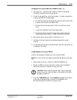
Setting the Conveyors Minimum Width Limit
(contd.)
4.
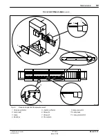
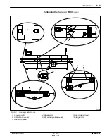
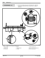
Inspect the drive chains (5 and 6) for excessive
stretching. Replace the chain if necessary.
5. Check for end play in the oven’s lead screws. To remove lead screw
end play, perform the following steps:
a. Remove the operator and hinged side access panels from the first
process module and the cooling module.
b. Remove the side access panels at the oven entrance and exit
ends.
c. Loosen the sprocket (4) set screw (hinged side).
d. Pull the lead screw towards the hinged side while pushing the
sprocket against the bearing. Tighten the sprocket set screw.
6. Manually set the conveyor width (1) to 50.8 mm (2 in.).
7. Set flags on the limit switch board halfway through their optical
sensors.
8. Connect the lead screws to the drive shafts. Mesh the miter gears (7)
and tighten set screws.
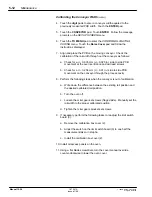
Calibrating the Conveyor Width
Perform the following to calibrate the ovens conveyor width:
NOTE: Do not move the rail unless all sprockets and gears are securely
set.
1. Apply power to the oven. Enter the
SET-UP SCREEN menu.
2. Measure a PCB to use as a reference. Set the ovens rail width to
that known dimension. Start the conveyor moving.
CAUTION: Before selecting product width, remove all boards
curing in the oven. Failure to observe this caution will result in
damage to equipment.
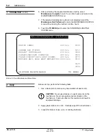
3. Touch the PRD WIDTH pad. Touch ENTER to calibrate the conveyor.
Follow the message prompts on the
SET-UP SCREEN menu.
Remove all boards from within the process cavity.
Summary of Contents for 107 041A
Page 1: ...Select Cure 100 Inch IR Oven Part 107 041A NORDSON CORPORATION D AMHERST OHIO D USA ...
Page 9: ...E 1995 Nordson Corporation All rights reserved Issued 11 95 12 28s1 Section 1 Safety ...
Page 10: ...Safety 1 0 E 1995 Nordson Corporation All rights reserved Issued 11 95 12 28s1 ...
Page 148: ...Parts 7 0 E 1996 Nordson Corporation All rights reserved 107 041A Issued 1 96 Manual 12 28 ...

