Installation
A 1-22
E
2000 Nordson Corporation
All rights reserved
41-3000
V
Issued 5/00
A3EN-04-[3V-A-AAXP]-12
7. Connect the output wires to the plug for terminal block TB2 from the
ship-with kit. Refer to Table A 1-3.
Table A 1-3 Output Contact Connections
Output Contact as
Labeled on Power
Behavior of Contact
TB2 Positions
Labeled on Power
Board
Unit Power Off
Unit Power On
TB2 Positions
(see Note A)
Warning Contact
(System Warning)
Open
Closed
(no warning)
Open
(warning exists)
1, 2
Fault Contact
(System Fault)
Open
Closed
(no fault)
Open
(fault exists)
3, 4
Ready Contact
(System Ready)
Open
Open
(unit not ready)
Closed
(unit ready)
5, 6
NOTE A: The output contacts are not polarity sensitive. It does not matter which wire is inserted into a position.
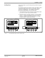
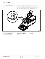
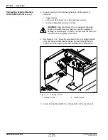
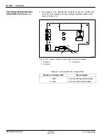
8. Connect the plug to TB2. See Figure A 1-13 for the location of TB2.
9. Go to the next procedure,
Connecting External Devices to the Pattern
Control
.
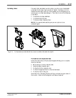
This procedure describes how to connect the following devices that
operate pattern control features:
S
a trigger device, which controls the operation of automatic gun
solenoid valves or the gun driver used with the pattern control feature
S
an optional enable/disable device, which sends a signal from a
remote location to enable or disable the pattern controller
S
the solenoid valves or gun driver that is used to activate the guns on
outputs 1 and 2
Connecting Output Contacts
(Optional)
(contd.)
Connecting External Devices to
the Pattern Control

