Installation
3-7
Part 334598G03
E
2008 Nordson Corporation
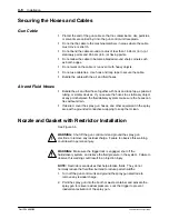
3. Unscrew the retaining ring (6). Remove the retaining ring and airless
cap (5) assembly.
4. Make sure the gasket or gasket with restrictor (3) is installed in the
nozzle (4).
NOTE:
If you are using a gasket with restrictor, the restrictor will already be
installed in the gasket. Make sure the gasket with restrictor is installed in
the nozzle with the flush surface toward the nozzle.
5. Install the PTFE retaining washer (2) behind the gasket to hold it in
place. The end of the fluid tip (1) can be used to help seat the gasket
and washer.
1
5
4
6
3
2
7
Figure 3-5
Nozzle and Gasket with Restrictor Installation
1. Fluid tip
2. PTFE retaining washer
3. Gasket or gasket with restrictor
4. Nozzle
5. Airless cap
6. Retaining ring
7. Electrode
6. Align the slot in the nozzle with the tab in the airless cap. Make sure to
line up the holes for the electrode (7).
7. Insert the electrode though the nozzle and airless cap making sure the
short leg of the electrode is inserted into the second hole in the back of
the nozzle.
8. Make sure the airless cap rests in the groove in the bottom of the
retaining ring and that it rotates freely.
9. Screw the retaining ring and cap assembly onto the extension. Hold the
cap in the desired position and tighten the retaining ring until it is snug.
NOTE:
The cap screws into the retaining ring and rests in a groove in the
ring that lets it rotate freely. Do not overtighten the cap.
Summary of Contents for kinetix
Page 6: ...Table of Contents iv Part 334598G03 E 2008 Nordson Corporation ...
Page 12: ...Safety 1 6 Part 334598G03 E 2008 Nordson Corporation ...
Page 24: ...Installation 3 8 Part 334598G03 E 2008 Nordson Corporation ...
Page 34: ...Maintenance 5 6 Part 334598G03 E 2008 Nordson Corporation ...
Page 60: ...Repair 7 20 Part 334598G03 E 2008 Nordson Corporation ...
Page 70: ...Parts 8 10 Part 334598G03 E 2008 Nordson Corporation ...
Page 75: ...Safety Note KINETIX TRILOGY ATEX Page 3 DOC13015B05 ...

