background image

Repair

6-11

E

2003 Nordson Corporation

All rights reserved

106 966C

Issued 6/03

Manual 12-27

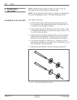
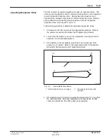
See Figure 6-8.

1. Roll the new air piston seal lip on a flat surface to form the seal lip (6).

The piston seal lip must hang down toward the film coater, as shown

in Figure 6-8, so the piston will fit properly in the piston insertion tool.

2. Coat the seal area of the piston insertion tool with Parker O-ring

lubricant or an equivalent lubricant.  Orient the piston assembly as

shown in Figure 6-8, then install it into the piston insertion tool.  Make

sure the entire assembly fits into the tool.

3. Make sure the air piston seal is round.  There should be no gaps or

folds between the piston insertion tool bore and the lip of the piston

seal.  Replace the piston seal if necessary.

1227019B

1

2

3

6

7

8

9

4

5

Fig. 6-8

Installing the air piston

1. Jam nut
2. Washer
3. Seal lock nut

4. O-ring
5. Piston insertion tool
6. Air piston

7. Needle
8. Coater body
9. Piston seal lip

Installing the Air Piston

Summary of Contents for Select Coat SC-204HS

Page 1: ...Select Coatr SC 204HS Non Circulating Film Coater Part 106 966C NORDSON CORPORATION D AMHERST OHIO D USA...

Page 2: ...Plus Blue Box ChromaFlex CleanSleeve CleanSpray Control Coat Cross Cut Easy Coat Econo Coat Flow Sentry Isocoil Isocore Iso Flo Nordson the Nordson logo PRX Pro Flo RBX Ready Coat Rhino Select Coat Se...

Page 3: ...7 Less Obvious Dangers 1 7 8 Action in the Event of a System or Component Malfunction 1 7 9 Maintenance and Repair 1 8 10 Material and Solvent Precautions 1 9 11 Disposal 1 12 1 Introduction 2 1 Move...

Page 4: ...Adjust Film Coater Cap and Extension 6 4 Removing the Needle Piston and Seals 6 5 Disassembling the Manifold 6 7 4 Rebuilding the Film Coater 6 8 Installing the U cup and Seals 6 8 Installing the Bus...

Page 5: ...1 Introduction 7 1 Using the Illustrated Parts List 7 1 2 Select Coat Non Circulating Film Coater Parts List 7 2 3 Service Kit Parts List 7 4 4 Nozzles Parts List 7 5 5 Nozzle Cleaning Kit Parts List...

Page 6: ...Table of Contents iv E 2003 Nordson Corporation All rights reserved 106 966C Issued 6 03 Manual 12 27...

Page 7: ...E 2003 Nordson Corporation All rights reserved Issued 11 95 A1EN 03 SF ELEC 2 Section 1 Safety...

Page 8: ...Safety 1 0 E 2003 Nordson Corporation All rights reserved Issued 11 95 A1EN 03 SF ELEC 2...

Page 9: ...g specific tasks and working with specific equipment S store this manual within easy reach of personnel installing operating maintaining or repairing this equipment S follow all applicable safety proc...

Page 10: ...smoking prohibited WARNING Wear protective clothing safety goggles and approved respiratory protection Failure to observe may result in serious injury WARNING Hot Risk of burns Wear heat protective cl...

Page 11: ...property and equipment damage Use this equipment only as described in this manual Nordson Corporation cannot be responsible for injuries or damages resulting from nonstandard unintended applications...

Page 12: ...utoff valves in the air supply lines to the system This allows you to relieve air pressure and lock out the pneumatic system before undertaking maintenance and repairs S Install a locking disconnect s...

Page 13: ...completed and check them for proper functioning Only qualified personnel physically capable of operating the equipment and with no impairments to their judgement or reaction times should operate this...

Page 14: ...onductive equipment objects being sprayed and fluid containers are connected to a true earth ground S Never touch exposed electrical connections on equipment while the power is ON S If you notice elec...

Page 15: ...ill corrode the equipment Operators should also be aware of less obvious dangers in the workplace that often cannot be completely eliminated S exposed surfaces on the equipment which may be hot or hav...

Page 16: ...equipment may void agency approvals and create safety hazards S Refer to the MSDS before using solvents to clean this equipment The MSDS will provide use storage and disposal information about the sol...

Page 17: ...off and lock out power as soon as the test is over S Do not attempt to service electrical equipment if there is standing water present Do not service electrical equipment in a high humidity environmen...

Page 18: ...ese cards are supplied with the equipment Additional cards are available free from Nordson Corporation WARNING Injection hazard Do not go near a known leak in a hose or fitting and stay clear of all d...

Page 19: ...Contact your solvent supplier to determine whether your existing materials and solvents contain halogenated hydrocarbons or to obtain a suitable nonhalogenated hydrocarbon solvent for cleaning and fl...

Page 20: ...ng Halogenated Fluids Chlorinated Solvents Iodinated Solvents Brominated Solvents Fluorocarbon Solvents Carbon Tetrachloride Ethyl Iodide Ethylene Dibromide Dichlorofluoromethane Chloroform Methyl Iod...

Page 21: ...E 2003 Nordson Corporation All rights reserved 106 966C Issued 6 03 Manual 12 27 Section 2 Description...

Page 22: ...Description 2 0 E 2003 Nordson Corporation All rights reserved 106 966C Issued 6 03 Manual 12 27...

Page 23: ...m coater SC 204HS is an applicator designed to be used with Control Coat and Select Coat nozzles It is used to apply materials that do not require heating and are thus not circulated It is air actuate...

Page 24: ...and an extension for mounting a nozzle Nordson Control Coat or Select Coat nozzles can be installed on the extension A gantry robot moves the basic SC 204HS film coater horizontally along the X and Y...

Page 25: ...ainer help prevent trigger air from leaking past the piston Any air that does leak past escapes through the weep hole in the front of the film coater cap The trigger air forces the piston upward until...

Page 26: ...seat Rotating the micro adjust cap counter clockwise increases the piston and needle travel which increases coating material flow Attach the manifold of the film coater to the head of the gantry robot...

Page 27: ...E 2003 Nordson Corporation All rights reserved 106 966C Issued 6 03 Manual 12 27 Section 3 Operation...

Page 28: ...Operation 3 0 E 2003 Nordson Corporation All rights reserved 106 966C Issued 6 03 Manual 12 27...

Page 29: ...t System Manual or the Select Coat High Volume System Manual 2 Check that the nozzle nut or nozzle are wrench tightened onto the film coater extension NOTE Attach Control Coat nozzles directly to the...

Page 30: ...e A clogged nozzle will cause restricted flow and pattern alteration If this problem occurs immerse the nozzle and nozzle nut if used in an appropriate solvent such as MEK Soak overnight before cleani...

Page 31: ...E 2003 Nordson Corporation All rights reserved 106 966C Issued 6 03 Manual 12 27 Section 4 Maintenance...

Page 32: ...Maintenance 4 0 E 2003 Nordson Corporation All rights reserved 106 966C Issued 6 03 Manual 12 27...

Page 33: ...d read the Material Safety Data Sheets MSDS for all materials used NOTE Do not expose the solenoid valve to solvents or coating material Solvents could damage the valve and coating material may clog i...

Page 34: ...reserved 106 966C Issued 6 03 Manual 12 27 5 Clean and dry the extension and body 6 Inspect the O rings hat seals U cup needle and seat Replace parts that are damaged or worn If you have removed the...

Page 35: ...E 2003 Nordson Corporation All rights reserved 106 966C Issued 6 03 Manual 12 27 Section 5 Troubleshooting...

Page 36: ...Troubleshooting 5 0 E 2003 Nordson Corporation All rights reserved 106 966C Issued 6 03 Manual 12 27...

Page 37: ...contains troubleshooting procedures These procedures cover only the most common problems that you may encounter If you cannot solve the problem with the information given here contact your local Nords...

Page 38: ...r using all new O rings and seals 2 Fluid leaks from nozzle or seat film coater on Nozzle or nozzle nut not securely tightened on extension Wrench tighten nozzle or nozzle nut on extension Be careful...

Page 39: ...ent or too low Check air pressure at workcell gauge Remove trigger air line from film coater and inspect for blockage If still no air pressure problem may be in robot controller Contact Nordson servic...

Page 40: ...Troubleshooting 5 4 E 2003 Nordson Corporation All rights reserved 106 966C Issued 6 03 Manual 12 27...

Page 41: ...E 2003 Nordson Corporation All rights reserved 106 966C Issued 6 03 Manual 12 27 Section 6 Repair...

Page 42: ...Repair 6 0 E 2003 Nordson Corporation All rights reserved 106 966C Issued 6 03 Manual 12 27...

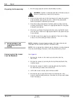
Page 43: ...al for an illustration and parts list S retaining ring removal tool S ring and seal insertion tool S piston insertion tool S base tool S module adjusting wrenches 2 Follow these procedures before disa...

Page 44: ...ilm coater micro adjust cap is adjusted to the correct setting make a note of the setting for future reference NOTE Handle O rings and seals carefully If O rings and seals are damaged the film coater...

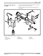
Page 45: ...ctrical connector from the solenoid valve 2 Remove the fillister screws 10 securing the manifold 9 to the Z axis slide 1227005B 1 2 3 5 6 4 10 9 7 8 Fig 6 1 Removing the rotating ring 1 Screw 2 Mounti...

Page 46: ...ul not to lose the flat washers and spring washers Place the washers on the blade of a small screwdriver for safekeeping 3 Remove the four screws 2 from the bronze bushing 7 at the extension end of th...

Page 47: ...ce the pronged end of the retaining ring removal tool supplied with the service kit under one of the tabs of the retaining ring 7 Gently lift up the tab to loosen the retaining ring The retaining ring...

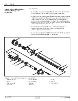
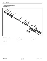
Page 48: ...12 27 1227007B 1 2 3 4 5 6 7 8 10 9 13 12 11 Fig 6 3 Removing the needle piston and seals 1 Jam nut 2 Washer 3 Seal lock nut 4 O ring 5 Air piston 6 Needle 7 Retaining ring 8 Backup seal 9 Hat seals 1...

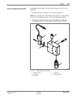
Page 49: ...fold 3 NOTE Do not expose the solenoid valve to solvents or coating material Solvents could damage the valve and coating material may clog it 2 Remove the solenoid valve 1 from the manifold 3 Inspect...

Page 50: ...this time 2 Place the flat washer 7 into the body on top of the U cup 8 Push on the washer with the base tool to seat the U cup into the bore The U cup should snap into place 3 Using the retaining ri...

Page 51: ...ne the hat seals for scratches cracks or tears If the hat seals are defective start with unformed hat seals and repeat steps 4 through 6 7 Insert the needle 1 into the piston side of the body module 5...

Page 52: ...the extension 4 carefully slide the bushing and extension into the film coater body 1 Be careful not to pinch the O ring during assembly 6 Inspect the bushing flange after installing it on the film c...

Page 53: ...ker O ring lubricant or an equivalent lubricant Orient the piston assembly as shown in Figure 6 8 then install it into the piston insertion tool Make sure the entire assembly fits into the tool 3 Make...

Page 54: ...rtion tool clockwise threading the seal lock nut onto the needle until the lip of the tool seats in the chamfer on top of the film coater body 8 9 Continue winding the piston into the bore until the t...

Page 55: ...the film coater with the appropriate material Refer to the system manual and the Easy Coat Programming manual 2 Look at the film pattern to see if it is acceptable See Figure 6 9 for examples of unacc...

Page 56: ...Carefully remove the film coater cap 5 4 Use an X acto knife or similar small tool to remove the retaining ring 8 Hold the flat washers 6 and spring washers 7 in place Be careful not to scratch or cut...

Page 57: ...rights reserved 106 966C Issued 6 03 Manual 12 27 1227011B 1 4 5 6 7 6 8 2 3 9 Fig 6 10 Adjusting the spring washers 1 Micro adjust cap 2 Locking nut 3 Preload screw 4 Screw 5 Coater cap 6 Washer 7 Sp...

Page 58: ...een the preload screw 3 and the flat washer 6 4 Continue tightening the screw the required number of turns see Figure 6 11 Reinstall the locking nut 2 5 Use the spanner wrench to turn the locking nut...

Page 59: ...he film coater 2 Place the film coater over the locating pins on the manifold 9 3 Secure the film coater to the manifold with the plate 2 and screws 1 1227013B 1 2 3 5 6 4 9 7 8 10 Fig 6 12 Installing...

Page 60: ...he screws at this time 3 Position the nozzle in the desired orientation 4 With the air cylinder fully retracted tighten the two screws 2 to clamp the rotating ring halves to the extension The top of t...

Page 61: ...ace the solenoid valve 1 on the manifold 3 over the gasket Place the solenoid mounting screws in the mounting holes see template and tighten it with the miniature Phillips head screwdriver shipped wit...

Page 62: ...aterial flowing through the seat Turning the micro adjust cap counter clockwise increases the piston and needle travel which increases the flow of coating material NOTE Do not open the micro adjust ca...

Page 63: ...E 2003 Nordson Corporation All rights reserved 106 966C Issued 6 03 Manual 12 27 Section 7 Parts...

Page 64: ...Parts 7 0 E 2003 Nordson Corporation All rights reserved 106 966C Issued 6 03 Manual 12 27...

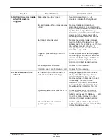
Page 65: ...e Description column gives the part name as well as its dimensions and other characteristics when appropriate Indentions show the relationships between assemblies subassemblies and parts Item Part Des...

Page 66: ...11 168 833 S S Nut seal lock 1 12 940 090 S S O ring Viton 0 218 x 0 344 x 0 063 in 1 13 115 055 S S Piston air 1 168 832 S S Ball seat extended 0 093 in 1 14 S S S Needle 1 15 S S S Extension seat SC...

Page 67: ...ector male 1 8 T x 10 32 NP 1 32 168 834 S Manifold SC 204 high speed 1 33 981 099 S Screw fillister hd 8 32 x 1 00 in sl zn 2 34 971 235 S Connector male Delrin 1 4 T x 1 8 NPT 1 NS 119 602 S Nut noz...

Page 68: ...0 13 in 1 22 986 115 S Ring retaining int 0 500 basic 1 23 168 825 S Spacer Delrin 0 703 x 0 535 x 0 04 1 24 709 774 S O ring Kalrez 0 375 x 0 500 x 0 062 in 1 NS 981 550 S Screw pan 5 40 x 0 312 in...

Page 69: ...120 072 Nozzle conformal coating 0 04 13 1 A NS 120 070 Nozzle conformal coating 0 04 14 1 A NS 120 074 Nozzle conformal coating 0 04 20 1 A NS 120 071 Nozzle conformal coating 0 06 24 1 A NS 120 068...

Page 70: ...0 074 120 075 B For use on nozzle parts 120 068 120 069 120 071 Item Part Description Quantity Note NS 094 000 Broach nozzle 0 003 in 1 A NS 094 002 Broach nozzle 0 008 in 1 B NOTE A For use on nozzle...

Page 71: ...E 2003 Nordson Corporation All rights reserved 106 966C Issued 6 03 Manual 12 27 Section 8 Specifications...

Page 72: ...Specifications 8 0 E 2003 Nordson Corporation All rights reserved 106 966C Issued 6 03 Manual 12 27...

Page 73: ...lating film coater 1227003B 192 5 mm 95 3 mm 3 75 in 7 58 in Fig 8 1 Approximate film coater dimensions NOTE Film coater extends from robot mounting surface approximately 5 715 cm 21 4 in Table 8 1 Fi...

Page 74: ...Specifications 8 2 E 2003 Nordson Corporation All rights reserved 106 966C Issued 6 03 Manual 12 27...
Reviews: