14
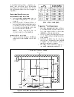
20"
(508 mm)
24 3/4"
(629 mm)
A/C or H/P
Coil
Wall
Panel
Coil Air
Filters
Return
Air
Grille
Floor
56"
(1423 mm)
29"
( 737 mm)
27"
(686 mm)
Furnace
Front
18"
Nearest
Wall or
Partition
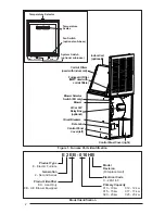
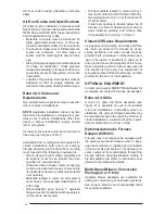
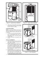
Figure 13. Typical Alcove Installation
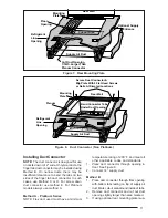
Figure 14. Typical Closet Installation
Wall-Mount
Return Air Grille
Holes (4)
Closet
Door
4.
Attach return air grille to frame assembly by
hooking grille over flange on top of frame
and into channel on bottom.
Closet Installation
NOTE: For closet installations, the return air
grille mounting frame is not used since the
furnace is located inside the closet (see Figure
14 and 15).
1.
Cut return air opening in desired position in
door or wall, preferably above top of fur-
nace. Refer to Table 1 for return air opening
requirements.
2.
Insert four fasteners, securing grille to door
or wall.
Furnace Installation
1.
Install 240V supply circuit(s) and 24V wir-
ing to closet or alcove (see Figure 16 for
appropriate locations).
2.
Remove refrigerant line knockouts in fur-
nace only when installing indoor coil of an
air conditioner or heat pump system, or for
hook-up of a VentilAire accessory when
the furnace is used in the upflow position.
Refer to instructions supplied with acces-
sory equipment.
3.
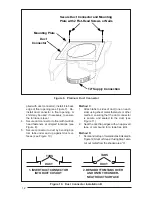
Remove unit front door and slide back until
bottom slots in rear of unit engage with both
tabs of optional rear mounting plate, OR...
If mounting plate is not used, an equivalent
method of securing the rear of the unit may
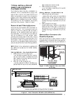
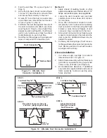
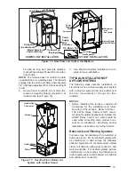
Figure 15. Closet Installation
0" Side
Clearance
to Furnace
Cabinet
Provide min. 235
sq. in. (1516 cm )
open free area in
front or side wall
or in top of
closet door
CLOSET DOOR
6"
(152 mm
)
0" Side
Clearance
to Furnace
Cabinet
Provide min. 250
sq. in. (1613 cm
2
)
open free area in
front or side wall
or in top of
closet door
CLOSET DOOR
1"
(25 mm)
Standard Closet Installation
Special 1" Clearance


