31
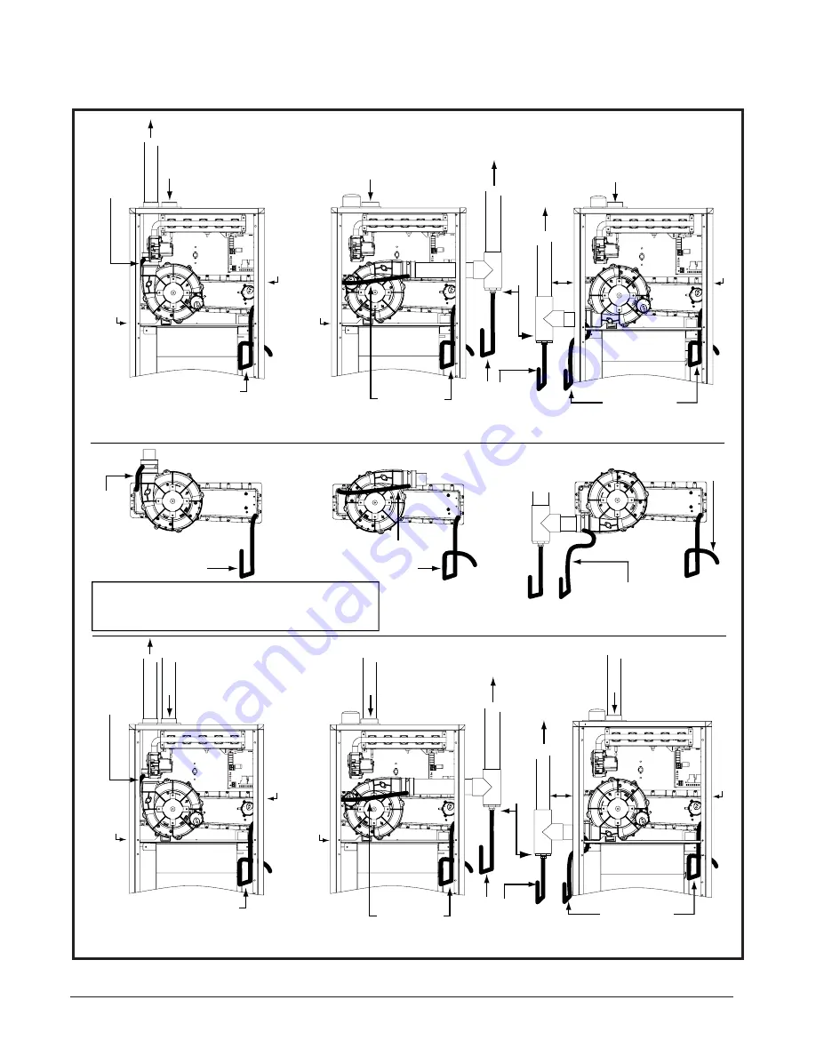
Figure 27. Upfl ow Options
1 Pipe Upflow
2 Pipe Upflow
PVC
Cap
Inlet Air
Inlet Air
Exhaust V
ent
Inlet Air
Inline Drain
Plug
Option
1
Option
3
Option
4
Option
5
VIEW -A-
VIEW -B-
VIEW -C-
Inlet Air
Inline
Drain
Inlet Air
Inlet Air
Plug
Plug
Header Box Drain
Plug
Exhaust V
ent
Exhaust V
ent
See View
-A-
See View -A-
See View -B-
Drain Line
Attached to
3/4 x 1/2
Hose Barb
PVC TEE
and Reducer
PVC
Cap
Exhaust V
ent
Plug
Plug
See View
-A-
See View -A-
PVC
Cap
Plug
Exhaust V
ent
See View -B-
Drain Line
Attached to
3/4 x 1/2
Hose Barb
PVC TEE
and Reducer
Option
2
X
See View -C-
Inline Drain
(This drain not needed
if “X” is less than 6”.)
Option
6
Plug
Exhaust V
e
nt
PVC
Cap
X
Header
Box Drain
(Tubing is routed thru the
blower deck and side of cabinet.)
Header Box Drain
1.) All drain lines must be trapped with J-Trap or field supplied loop.
2.) Drain line traps may be positioned inside or outside the cabinet.
3.) PVC Cap is optional for options 1,2 and 3 only.
NOTES:
See View -C-
(Tubing is routed thru the
blower deck and side of cabinet.)
VENTING INFORMATION


