23
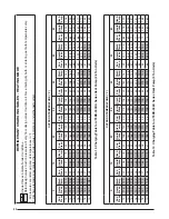
Figure 13. JT5BD Wiring Diagram
T1
T2
C
Y
O
W2
R
DFT
E
DF1
DF2
O
LPS
(IF EQ
UIPPED)
DEFR
OST CONTR
OL BO
ARD
DEFR
OST
THERMOST
A
T
CONT
A
C
T
O
R
REVERSING
VA
LV
E
SELENOID
H
C
S
R
C
S
R
T1
T2
T3
F
T1
T2
L2
L1
CCH
(IF EQ
UIPPED)
COMPRESSOR
OUTDOOR F
A
N MO
T
O
R
GR
OUNDING
LUG
SINGLE PHASE
FIELD SUPPL
Y
PTCR
C
BLA
CK
BLA
CK
RED
RED
BLA
C
K
BLA
C
K
BLAC
K
BLUE
ORANGE
ODT (IF
EQ
UIPPED)
YELLO
W
YELLO
W
YELLO
W
PTCR
(If equipped)
CC
LLS
(IF
EQ
UIPPED)
¢710805ª¤
LPS
(IF EQ
UIPPED)
BLA
CK
YELLO
W
RED
YELLO
W
BLUE
BLAC
K
BLACK
WIRING DIA
GRAM
7108050
04/08
Split System Heat Pump (Outdoor Section)
NO
TES:
1.
Disconnect
all
po
wer
bef
ore
ser
vicing.
2.
For suppl
y
connections use copper conductor
s
onl
y
.
3.
Not suitab
le
on systems that e
xceed
150 v
olts
to gr
ound.
4.
For replacement wires use conductor
s
suitab
le
fo
r
105 C.
5.
For ampacities and o
v
er
current
pr
otection,
see unit rating plate
.
6.
Connect to 24 v
a
c/40v
a
/c
lass
2 cir
c
uit.
See furnace/air handler
instructions f
o
r
contr
o
l
cir
c
uit
and optional rela
y/transf
ormer
kits.
7.
DO NO
T install a Har
d
Star
t Kit on a model with a PTCR installed.
1.
Couper le courant a
v
ant de faire letretien.
2.
Emplo
y
ez uniquement des conducteur
s en cuivre
.
3.
Ne con
vient pas aux installations de plus de
150 v
o
lt a la terre
.
Single Phase
OPTIONAL HARD ST
AR
T KIT
Star
t
Capacitor
2
5
Star
t
Rela
y
1
to
T1 on contactor
to
“H”
on capacitor
to T2
on
contactor
Red
Y
ello
w
Blac
k
Y
ello
w
Leg
e
nd
Field Wiring
F
a
ctor
y Wiring:
Lo
w V
o
lta
g
e
High V
o
lta
g
e
CC - Contactor Coil
CCH - Crankcase Heater (If Equipped)
DFT - Defr
ost
Thermostat
LLS - Liquid Line Solenoid (If Equipped)
R
VS - Re
ver
s
ing
V
a
lve Solenoid
ODT - Outdoor
Thermostat (If Equipped)
LPS - Lo
w Pressure Switc
h (If Equipped)
1
2
3
4
Closing during defr
ost.
R
a
ti
n
g
:
1
A
m
p
. Max.
Opens
during
defr
o
st.
R
a
ti
n
g
: 2
H
P
a
t 2
3
0
V
a
c
M
a
x
.
Closed when "Y" is on.
Open when "Y" is off
.
Pr
o
vides "off" dela
y time of 5 min.
when "Y" opens.
With DFT c
losed and "Y" c
losed,
compressor run time is accum
ulated.
Opening of DFT during defr
ost or inter
v
al period resets the inter
v
a
l to 0.
Defr
ost Boar
d
Operation:
Dual Capacitor
Compressor
Contacts
Compressor
Outdoor F
a
n Motor
R
C
S
S
C
R
L1
T1
T2
ODT
(IF EQ
UIPPED)
Lo
w
Vo
lt
a
g
e
T
e
rminals
E
Defr
ost Contr
ol Boar
d
DFT
Contr
o
l
Logic
CC
DF1
DF2
DFT
1
2
3
4
1
R
W2
O
Y
C
T2
T1
R
W2
O
Y
C
RV
S
LLS (IF
EQ
UIPPED)
PTCR (If equipped)
H
C
F
PTCR - P
ositive
T
emperature
Coefficient Resistor
L2
CCH
ELECTRICAL INFORMATION

