29
Transformers open on primary indicate low voltage short
circuit. Transformers open on secondary indicate an overload
(a current draw that exceeded rating).
Low Voltage Wiring
Install the thermostat per the manufacturer's instructions. The
low voltage (24 vac) connections from the thermostat are
made at the pigtail wires coming off the control board in the
furnace. See Figure 23 for the proper connections for heating
only (two-wire) and heating/cooling (four-wire) applications.
The recommended minimum wire gauge for thermostat wiring
is shown in Table 5.
The thermostat must not be installed on an outside wall or any
other location where its operation may be adversely affected.
Adverse effects include radiant loading from fireplaces, sun-
light, or lighting fixtures, and convective loading from warm air
registers or electrical appliances.
To check the heat anticipator setting:
Jump out R to W at thermostat with 10 Loop Helex and
measure current draw after blower starts. Divide by 10.
Example: 4 Amps = .4 set at .4.
Limit Control (Picture 14) – This furnace is protected by two
high temperature safety limit switches. The auxiliary (upper)
limit switch and the high temperature (lower) limit switch are
automatic reset types. If either limit trips, the burner will shut
off, and status light will flash “1”.
M1M-Control Board Replacement
Replace the control board only after determining a failure has
occurred in it. Most problems that are blamed on control are
actually external to control. (See troubleshooting section). If
control has failed, use the following procedure to replace.
1.
Disconnect power to unit by turning off power switch.
2.
Disconnect molex plugs and all push on terminal
connections. Note connections for rehook up.
3.
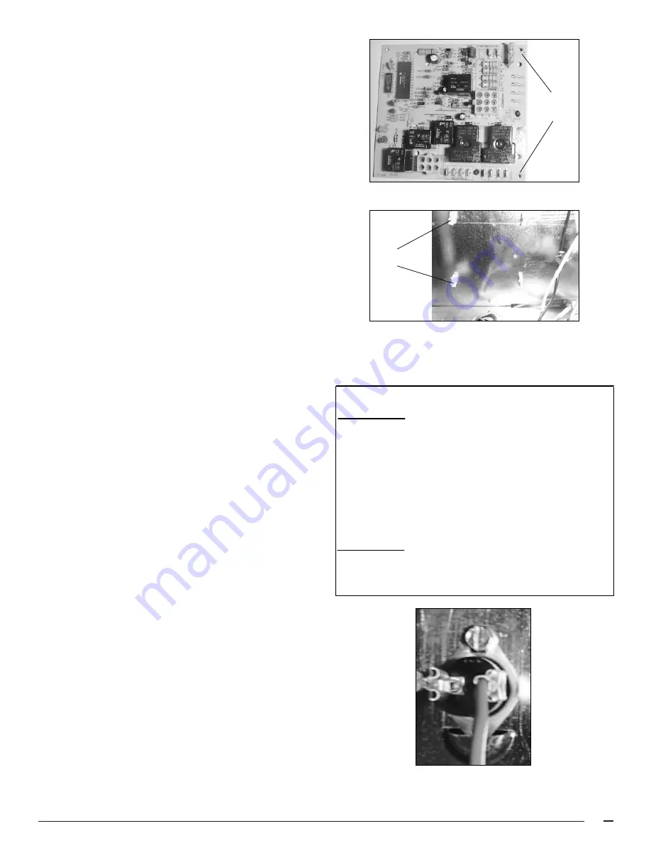
After all wire connections have been removed you must
squeeze the four white stand offs to remove board. See
Pictures 13 showing board removed with exposed
standoffs remaining.
4.
Carefully line up holes (Picture 12) on the new board over
standoffs, and push into place. Caution: push from
outside edge only - be careful of fragile components.
5.
Reinstall all molex plugs and wires removed in step 2.
6.
Apply power and re-test.
Ignition Control Troubleshooting
RED
Steady ON
Control OK
Steady OFF
No power
Rapid Flash
False flame or internal control fault
1 Flash
Limit switch is open
2 Flashes
Pressure switch is open with inducer on
3 Flashes
Pressure switch is closed with inducer off
4 Flashes
Lockout due to failed ignition
5 Flashes
115 vac & neutral reversed or no ground
YELLOW
Steady ON
Good Flame Signal
Blinking
Weak Flame Signal
Steady OFF
No Flame Signal
CONTROL LIGHT STATUS
Picture 14. Limit Switch
Picture 12. UTEC Ignition Control
Stand off
Holes
Picture 13. Ignition Board Removed
Stand offs


