background image

14

furnace is equal to the return air supply under normal, 
indoor return air applications.

•  When  a  cooling  system  is  installed  which  uses  the 

furnace blower to provide airflow over the indoor coil, 
the coil must be installed downstream (on the outlet 
side) of the furnace or in parallel with the furnace.

•  If  a  cooling  system  is  installed  in  parallel  with  the 

furnace, a damper must be installed to prevent chilled 
air from entering the furnace and condensing on the heat 
exchanger. If a manually operated damper is installed, 
it must be designed so that the furnace will not operate 
when the damper is in the cooling position or when in 
heating position, the cooling system is inoperable.

•  It  is  good  practice  to  seal  all  connections  and  joints 

with industrial grade sealing tape or liquid sealant. 
Requirements for sealing ductwork vary from region 
to region. Consult with local codes for requirements 
specific to your area.

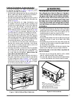
Return Air Connections

In applications where the supply ducts carry heated air to 
areas outside the space where the furnace is installed, 
the return air must be delivered to the furnace by duct(s) 
secured to the furnace casing, running full size and without 
interruption.

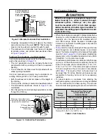
•  Upflow furnaces draw the return air from the base of 

the furnace. A stand or return air duct must be supplied 
to the furnace to provide the required return air.

•  Downflow models draw the return air from the top of 

the furnace. The minimum required clearance to the top 
of the furnace is detailed on the furnace rating plate. 
Additional clearance may be required depending upon 
filter accessibility.

For each U.S.A. application, the home manufacturer 
shall comply with all of the following conditions to have 
acceptable return air systems for closet installed forced 
air heating appliances:

•  Regardless of the location, the return air opening into the 

closet shall not be less than specified in the appliance’s 
listing.

•  Means shall be provided to prevent inadvertent closure 

by a flat object placed over the return air opening when 
it is located in the floor of the closet (versus the vertical 
front or side wall).

•  The  cross-sectional  area  of  the  return  duct  system 

leading into the closet shall not be less than 390 in

2

.

•  The total free area of openings in the floor or ceiling 

registers serving the return air duct system must be at 
least 352 in

2

. At least one register should be located 

where it is not likely to be covered by carpeting, boxes 
and other objects.

•  Materials located in the return duct system must have a 

flame spread classification of 200 or less. This includes 
a closet door if the furnace is in a closet.

•  Noncombustible pans having 1" upturned flanges are 

located beneath openings in a floor duct system.

•  Wiring materials located in the return duct system shall 

conform to Articles 300-22 of the National Electrical 
Code (ANSI C1/NFPA-70).

•  Gas piping is not run in or through the return duct system.
•  Test the negative pressure in the closet with the air-

circulating fan operating at high speed and the closet 
closed. The negative pressure is to be no more negative 
than minus 0.05 inch water column.

•  Air conditioning systems may require more duct, register 

and open louver area to obtain necessary airflow. Use 
NORDYNE’s certiduct program to determine proper 
duct size for A/C.

•  For  floor  return  systems,  the  manufactured  home 

manufacturer shall affix a prominent marking on or 
near the appliance where it can be easily read when 
the closet door is open. The marking shall read:

 CAUTION:

HAZARD OF ASPHYXIATION:

 Do not cover or 

restrict return air opening.

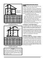
Supply Air Connections

For proper air distribution, the supply duct system must be 
designed so that the static pressure measured external 
to the furnace does not exceed the listed static pressure 
rating shown on the furnace rating plate. 

The  supply 

air must be delivered to the heated space by duct(s) 

secured to the furnace casing, running full size and 

without interruption.

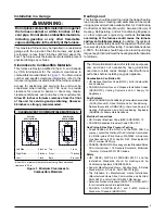
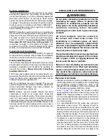
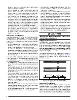
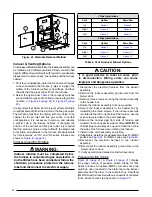
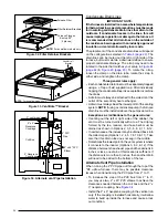
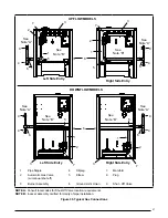
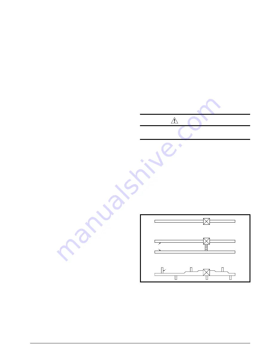
Three typical distribution systems are shown in 

Figure 11

The location, size, and number of registers should be 
selected on the basis of best air distribution and floor 
plan of the home.

Figure 11

A Single trunk duct

B

Dual trunk duct

w/crossover connector

C

Transition duct

   w/branches

Figure 11. 

Typical Supply Duct System

Acoustical Treatments

Damping ducts, flexible vibration isolators, or pleated 
media-style filters on the return air inlet of the furnace 
may be used to reduce the transmission of equipment 
noise eminating from the furnace. These treatments can 
produce a quieter installation, particularly in the heated 
space. However, they can increase the pressure drop in 

Summary of Contents for M4RC-072D-35C

Page 1: ...department RISQUE D INCENDIE OU D EXPLOSION Le non respect des avertissements de s curit pourrait entra ner des blessures graves la mort ou des dommages mat riels L installation et l entretien doivent...

Page 2: ...loor Openings 16 Installing Finger Tabbed Duct Connectors 16 Narrow Duct Attachment Option 1 17 Narrow Duct Attachment Option 2 17 Installing Screw Down Duct Connectors 18 Installing the Downflow Furn...

Page 3: ...rovide adequate combustion and ventilation air to the furnace space as specified on pages 6 9 Provide adequate clearances around the vent air intake terminal as specified in Figure 7 page 11 Figure 8...

Page 4: ...mestic hot water equipment where the bottom of the vent terminal and the air intake is installed above four feet above grade the following requirements must be satisfied a A CO detector and alarm shal...

Page 5: ...Electrical Code NEC ANSI NFPA 70 CANADA Canadian Electrical Code CSA C22 1 Gas Piping Gas Pipe Pressure Testing Current edition of the NFGC and the NFPA 90B For copies contact the National Fire Prote...

Page 6: ...QUE D EMPOISONNEMENT AU MONOXYDE DE CARBONED Le non respect des consignes suivantes portant sur chacun des appareils raccord s au syst me d vacuation mis en service pourrait entra ner l empoisennement...

Page 7: ...htly sealed to the furnace The required sizing of these openings is determined by whetherinsideoroutsideairisusedtosupportcombustion the method by which the air is brought to the space and by the tota...

Page 8: ...ustion Air Drawn from Inside Total Input Rating Btuh Minimum Free Area Each Opening Round Duct Diameter 40 000 100 sq In 12 inches 60 000 100 sq In 12 inches 80 000 100 sq In 12 inches 100 000 100 sq...

Page 9: ...ntly adopted by the NFGC uses one opening within 12 inches of the top of the space This method may be used if it is acceptable to the local codes The following conditions must be met 1 The opening mus...

Page 10: ...onofthefurnacecombustionsystem See list of substances on page 4 Route piping as direct as possible between the furnace and the outdoors Horizontal piping from inducer to the flue pipe must be sloped 1...

Page 11: ...rotection see page 12 Figure 7 12 min to maximum expected snow level both pipes 90 Elbow Exhaust vent option B Exhaust vent option A Mounting kit faceplate secured to wall with screws both pipes Combu...

Page 12: ...exposed to temperatures below freezing i e when it passes through unheated spaces chimneys etc the pipe must be insulated with 1 2 inch thick sponge rubber insulation Armaflex type insulation or equiv...

Page 13: ...ponsible for water leakage which occurs due to loose hose connections or improperly sealed drain line pipes CIRCULATING AIR REQUIREMENTS WARNING Do not allow combustion products to enter the circulati...

Page 14: ...in2 The total free area of openings in the floor or ceiling registers serving the return air duct system must be at least 352 in2 At least one register should be located where it is not likely to be c...

Page 15: ...and other documents supplied with the furnace and or optional air conditioningequipment Unlessitisnoteddifferentlyinthis manual onlyusefactoryauthorizedkitsandaccessorieson thisappliance Refertolocala...

Page 16: ...4 210 901991A 904012 10 1 4 260 901992A 904013 12 1 4 311 901993A 904014 NOTE Dimensions shown as Inches Millimeter Table 3 Duct Connector Sizes X FLOOR OPENING FLOOR CAVITY SUPPLY AIR DUCT Locating...

Page 17: ...form an opening for the duct connector applies to Options A or B 3 Installtheductconnectorwiththebottomtabsextending into the supply air duct 4 Bend the tabs on the bottom of the duct connector upward...

Page 18: ...y Air Duct Hole for Gas Line Wood Floor Bend tabs up 90 Figure 18 Screw Down Duct Connector Figure 20 Figure 20 A C Coil Box Installation D O N O T I N S T A L L S C R E W S I N T H I S S U R F A C E...

Page 19: ...f drilling screws secure the bracket to the A C coil box and the furnace Repeat for other side of furnace 5 Position the plenum on top of the coil box and secure together with sheet metal screws The s...

Page 20: ...have two switches one connected to the static tap on the inducer assembly and the other to the collector box Downflow M4RLSeries furnacesrequireonlyoneswitchconnected to the inducer s static tap as s...

Page 21: ...itch Accessories The components in Figure 27 Figure 28 page 22 Figure 29 Figure 30 are included in the extra parts bag that is supplied with the purchase of M4RC M4RL furnaces Depending on your partic...

Page 22: ...ield Supplied 2 PVC ELBOW Field Supplied PVC Trap 2 PVC Tee 2 x 1 2 PVC Reducer 1 2 x 1 2 Hose Barb 1 2 x 3 4 Hose Barb 2 PVC Pipe from Inline Drain Assembly Not Included 1 2 Tubing Formed into a Loop...

Page 23: ...to the finish flange or vent pipe with a hose clamp if using neoprene couplings Upflowfurnacesrequirethe3 neoprenecouplingclamps to be installed above the coil box Upflow Furnaces Combustion air and...

Page 24: ...secondary heat exchanger A drain must always be at the lowest point of the venting system NOTE Ifusingacondensatepump thefurnace drain line must be installed above the pumps water line Exceptions clar...

Page 25: ...ply with the latest edition of the National Fuel Gas Code ANSIZ223 1 or CAN CGAB149 1or 2 Installation Codes Some local regulations require the installation of a manual main shut off valve and ground...

Page 26: ...t t une solution savonneuse commerciale fabriqu esp cifiquementpurlad tectiondes fuites de gaz Un incendie ou une explosion peut entra ner des dommages mat riels des blessures ou la mort AVERTISSEMENT...

Page 27: ...Shut Off Valve location requirements NOTE B Inducer assembly omitted for clarity of pipe installation Figure 35 Typical Gas Connections 4 7 5 3 6 UPFLOW MODELS DOWNFLOW MODELS 9 2 See Note B 1 3 See...

Page 28: ...screw the orifices 7 into the gas manifold assembly 5 by hand until snug then tighten with a wrench 12 Install the appropriate LP Propane orifices 7 into the gas manifold assembly 5 13 Remove the pre...

Page 29: ...vent cross threading hand tighten the plug first then tighten with 3 16 Allen wrench Measuring the Manifold Pressure The manifold pressure must be measured by installing a pressure gauge Manometer Mag...

Page 30: ...t 105 F 40 C For electrical specifications refer to the furnace nameplate or Table 5 page 32 2 Check all gas connections for leaks with a soap and water solution If the solution bubbles there is a gas...

Page 31: ...s or 2 Measure the current flow on the thermostat R W circuit after the circulating blower motor has started The six pin terminal marked Expansion Port is not used in the single stage furnace as shipp...

Page 32: ...MOTOR CONNECTION FIELD WIRING LOW VOLTAGE CONNECTION R C Y G W NOTE The Y terminal on the control board must be connected to the thermostat for proper cooling mode operation Connect R W For Heating O...

Page 33: ...t gas per hr Local heating value of the gas obtained from gas supplier 1 040 Btu per cubic ft Input rate 1 040 x 90 93 600 Btuh Verifying Adjusting Input Rate IMPORTANT NOTE The input rate must not ex...

Page 34: ...l for cooling the contactorintheoutdoorcondensingunitisde energized and the control continues to run the fan for a period of 60 seconds Fan Mode When the thermostat energizes the G terminal for contin...

Page 35: ...rned open Is the gas turned on Are any manual reset switches open Is the filter dirty or plugged Is the flame sensor coated Remove and clean with steel wool Do not use emery cloth or sandpaper Is ther...

Page 36: ...ter s An air filter is supplied with the furnace as shipped from the factory It is recommended that filters be cleaned or replaced monthly during the heating season WARNING Never operate the furnace w...

Page 37: ...ng Bottom Return Opening RC Upflow Furnace Model s Dim A Dim B Dim C 054D 24B 17 1 2 15 7 8 16 1 8 072D 35C 21 19 3 8 19 5 8 090D 35C 108D 45D 24 1 2 22 7 8 23 1 8 NOTE Dimensions shown in inches A 34...

Page 38: ...1590 48 1555 49 1495 51 1435 53 1340 57 Low 1410 54 1390 55 1365 56 1330 58 1310 59 1275 60 1235 62 1210 63 RC090D 35C Side Return 90 000 High 2240 2175 35 2100 37 2040 38 1985 39 1910 40 1825 42 172...

Page 39: ...agnostic Description Low Flame Sensor Signal Flame Present FAULT CONDITIONS Yellow LED Continuous Flash On Alternating Flash Replaces 710915B IGNITOR INDUCER FLAME SENSOR C BLOWER LIMIT DOOR SWITCH R...

Page 40: ...44 220 439 84 43 214 429 86 42 209 419 88 41 205 409 90 40 200 400 92 39 196 391 94 38 191 383 96 38 188 375 98 37 184 367 100 36 180 360 102 35 176 353 104 35 173 346 106 34 170 340 108 33 167 333 11...

Page 41: ...3 0 Manifold Pressure 9 000 to 9 999 FT 49 49 49 49 Orifice Size 2 8 2 8 2 8 2 8 Manifold Pressure Table 12 Table 12 High Altitude Deration Chart for Natural Gas Low Heating Value NATURAL GAS LOW HEAT...

Page 42: ...air supply inlet to building or the combustion air inlet to any other appliance 6 inches 15cm for appliances 10 000 Btuh 3kW 6 inches 15cm for appliances 10 000 Btuh 3kW 4 ft 1 2m below or to side of...

Page 43: ...Close to Furnace as Possible 2 x 3 Neoprene Couplings with 2 Hose Clamps Upward Pitch 1 4 Per Foot Exhaust Vent 5 3 Combustion Air Vent Pipe 7 3 x 90 Elbows 3 x 90 Elbow Exhaust Vent 3 Exhaust Vent St...

Page 44: ...STION AIR X See NOTE 5 X See NOTE 5 PVC Tee PVC Trap X See NOTE 5 X See NOTE 5 PVC Tee PVC Trap Collector Box Drain Factory Equipped See NOTE 2 Inline Drain Field Supplied See NOTES 2 3 Drain Line Att...

Page 45: ...PE Inline Drain Factory Supplied See NOTE 4 Collector Box Drain Factory Equipped See NOTE 2 Inline Drain Factory Supplied See NOTE 4 Collector Box Drain Factory Equipped See NOTE 2 Drain Line Attached...

Page 46: ...controls the flow of gas to the burners When the gas valve is energized it automatically opens and regulates the gas pressure in the manifold Inducer Assembly The inducer assembly vents products of co...

Page 47: ...47...

Page 48: ...nstructions to the customer s package for future reference ELECTRICAL SYSTEM Electrical connections tight YES NO Line voltage polarity correct YES NO Supply Voltage _________________________________ V...

Reviews: