8
IMPORTANT:
If the webbing is not removed, the
condensate will not drain properly and ceiling damage
may occur.
3. Insert the plug (from horizontal drain pan) into the open
and unused drain hole in the drain pan at the bottom
of the unit to block bypass air.
4. Remove the corresponding drain line knockout from
the coil access door to allow access to the horizontal
drain.
5. Replace the door and attach the drain line.
Horizontal Right Installations
1. Remove the coil access door. Unscrew the line-set tube
close-off plate from the front left cabinet rail.
2. Slide the coil and drain pan assembly out of the unit.
3. Remove the sheet metal hairpin covers (if supplied)
from the back of the coil and discard.
4. Place the horizontal drain pan on the opposite side of
the coil. On units with 2 sets of knockouts, remove the
other set of knockouts in the coil spacing plates and
insert support rod.
5. Slide the coil and the horizontal drain pan assembly
back into the unit. Re-attach the tube close off plate.
6. Remove the plug from one of the threaded holes
in the horizontal drain pan. Completely remove the
webbing located in the threaded holes of the drain
pan.
IMPORTANT:
If the webbing is not removed, the
condensate will not drain properly and ceiling damage
may occur.
7. Insert the plug (from horizontal drain pan) into the open
and unused drain hole in the drain pan at the bottom
of the unit to block bypass air.
8. Remove the corresponding drain line knockout from
the coil access door to allow access to the horizontal
drain.
9. Replace the door and attach the drain line.
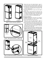
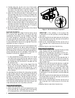
4. Carefully place the cased coil on top of the modular
air handler.
NOTE:
Make sure the units are fl ush in the
front and on the sides with a “step” fi t in the back and
that there are no gaps on the sides. See Figure 4.
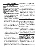
5. Attach the front joining bracket to the cased coil and
the air handler. Align the screw holes in the bracket with
the holes where the lower front bracket and lower tie
bar were attached.
6. Secure the bracket to the modular unit and the cased
coil with the screws removed earlier in steps 1 & 2.
7. Attach the rear joining bracket to the backside of the
modular unit. Position the bracket so that it is fl ush with
the sides and back of the units with the 1/2” insulation
facing the rear gap between the units.
8. Secure the rear bracket to the modular unit and cased
coil with self-tapping screws.
Horizontal Installation
MB6 indoor blowers are shipped from the factory ready
for horizontal left applications and horizontal right
applications. The blowers can be installed horizontally
in an attic, basement, crawl space or alcove. They can
also be suspended from a ceiling in a basement or utility
room in either a right to left airfl ow or left to right airfl ow.
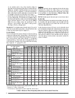
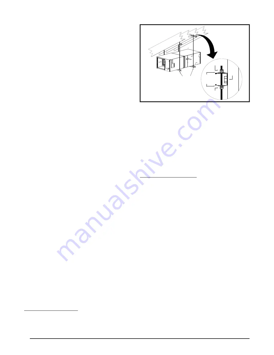
A typical installation of the unit in a suspended horizontal
application is shown in Figure 5.
When mating the blower and coil for horizontal left or right
applications, reference the upfl ow mating directions on
pages 6 & 7. Make sure to account for the coil orientation
by confi guring the coil drain pan assembly properly. Multi-
position procedures are also available in the cased coil
Installation Instructions supplied with the unit.
NOTES:
• In many applications when joined with a C6 cased
coil, the shorter horizontal drain pan extension which
is included with the MB6 must be used. This is to avoid
any interference with the extension included with the
C6 and the blower.
• indoor blowers may or may not be shipped from the
factory with all the parts required for horizontal left
applications and horizontal right applications. If your
unit does not have parts for a horizontal application, a
kit is available.
If suspending the indoor blower from the ceiling, assemble
a support frame (Figure 4) using slotted iron channel and
full threaded rod. Fasten the frame together with nuts,
washers, and lockwashers. Secure the support frame to
the rafters with lag bolts. The indoor blower can also be
suspended using steel straps around each end of the unit.
The straps should be attached to the indoor blower with
sheet metal screws and to the rafters with bolts.
Horizontal Left Installations
1. Remove the coil access door.
2. Remove the plug from one of the threaded holes in the
horizontal drain pan. Completely remove the webbing
in the threaded holes of the horizontal drain pan.
Figure 5. Unit Horizontally Suspended
Threaded
Rod
Lag
Bolt
Nuts (x2)
Washer
and
Lockwasher
Nuts (x2)


