background image

6

around penetrations into the air handler, such as for 
electrical wiring.

Air Filters

 WarninG:

never operate the air handler without a filter 
or with doors removed. dust and lint can build 
up on internal components, resulting in loss of 
efficiency, equipment damage, and possible fire.

MB7 Series air handlers are not equipped with filter 
racking; however, NORDYNE strongly recommends that 
a filter be located in the return air duct system. Installing 
the filter and replacing it every 3 months will increase air 
quality throughout the home.

Unconditioned Spaces
All duct work passing through unconditioned space must 
be properly insulated to minimize duct losses and prevent 
condensation. Use insulation with an outer vapor barrier. 
Consult your Distributor for the recommended type and 
thickness of insulation for your area as required by local 
codes.

condensate drainage

 caution:

the air handler must be level to ensure proper 
condensate drainage. an unlevel installation 
may result in structural damage, premature 
equipment failure, or possible personal injury.

•  Modular  air  handlers  are  intended  to  be  mated  with 

specific NORDYNE C6 cased coils. To ensure proper 
condensate drainage, the unit must be installed in a 
level position within 1/4 inch over the height, width, and 
depth of the unit. The best system performance will be 
obtained if the unit is located in a centralized position 
with respect to the air distribution system. Refer to the 
Installation Instructions supplied with the Cased Coil 
for proper condensate drain connections.

•  If the air handler is located in or above a living space 

where damage may result from condensate overflow, 
an auxiliary drain pan should be installed under the unit. 
A separate drain line should extend from the pan to a 
conspicuous point and serve as an alarm indicating 
that the primary drain is restricted. As an alternative to 
a separate drain line, an approved water level indicator 
or float switch device should be used to shut down the 
unit in the event water is detected in the auxiliary pan.

•  During  system  checkout,  inspect  the  drain  line  and 

connections to verify proper condensate drainage.

•  Methods for disposing of condensate vary according 

to local codes. Refer to local codes or authority having 
jurisidiction for restrictions and proper condensate 
disposal requirements.

air Handler inStallation

The MB7 Series air handler is shipped ready for vertical 
upflow installation and is approved for attic, basement, 
alcove/closet or crawlspace installation with zero clearance 
to combustibles. They may also be applied in downflow 
or horizontal left and right discharge applications. See 
Table 1 (page 4) for required installation clearances. this 
appliance is approved only for indoor use.

note: For shipping purposes, the front and rear joining 
brackets are located in the unit’s heater box. Remove 
these two items from the heater box before beginning.

•  The unit must be leveled at installation and attached to 

a properly installed duct system.

•  The surface that the air handler is mounted on must 

provide sound physical support of the unit.

•  The air handler must be installed so that all electrical 

components are protected from water.

•  If a louvered door is installed across the front of this 

unit, the appliance must be mounted flush or behind 
front edge of finished wall.

• 

Modular air handlers are intended to be mated with 
specific NORDYNE C6 cased coils. Reference the 
Technical Specifications for coil mating combinations.

upflow installation
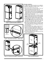
The MB7 Series air handler is shipped from the factory 
ready for upflow configuration as shown in Figure 1 (page 
7). Return air must must enter from the bottom of the unit.

1. Remove the bracket above the door of the cased coil. 

Retain the screws for later use. note: Before mating 
the modular unit with the cased coil, clean the mating 
surfaces on both units and apply the black neoprene 
gasket tape to the top of the coil case (except the rear 
surface). Make sure there are no gaps on the front and 
side flanges.

2. Carefully place the modular air handler on top of the 

cased coil making sure not to damage the cased coil 
flanges. The units will be flush in front with an overhang 
in the back as shown in Figure 2 (page 7).

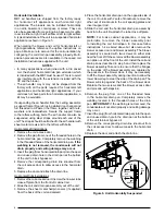
3. Remove the lower front bracket (Figure 3, page 7) from 

the modular unit. Retain the screws for later use.

4. Attach the front joining bracket to the front of the modular 

unit. Align the screw holes in the bracket with the holes 
from the lower front bracket and the top panel of the 
coil case. See Figure 3.

5. Secure the bracket with the screws removed earlier in 

steps 1 & 2.

6. Attach the rear joining bracket to the backside of the 

modular unit and cased coil. Position the bracket so that 
it is flush with the sides and back of the units with the 
1/2” insulation facing the rear gap between the units.

7. Secure the rear bracket with self tapping screws.

Summary of Contents for MB7BM Series

Page 1: ...nt role as well Pay attention to all safety warnings and any other special notes highlighted in the manual Improper installation of the furnace or failure to follow safety warnings could result in ser...

Page 2: ...ing 11 Turning the Blower Off 11 Blower Configurations 11 Selecting minimum Electric Heat Airflow 11 Determining Nominal System Capacity 11 3 speed Units 11 High Efficiency Units 12 Selecting Basic He...

Page 3: ...ment Do not store any of the following on or in contact with the unit Rags brooms vacuum cleaners or other cleaning tools spray or aerosol cans soap powders bleaches waxes cleaning compounds plastics...

Page 4: ...dbesetintopositionbeforerouting the refrigerant tubing Operation of an Air Handler During Construction CAUTION Failure to follow these instructions will void the factory warranty and may significantly...

Page 5: ...tments must be constructed and installed in accordance with NFPA and SMACNA construction standards Consult with local codes for special requirements For best sound performance be sure to install all t...

Page 6: ...nts air handler INSTALLATION The MB7 Series air handler is shipped ready for vertical upflow installation and is approved for attic basement alcove closetorcrawlspaceinstallationwithzeroclearance to c...

Page 7: ...ne gasket tape to the top of the air handler NOTE The blowers flanged surface is now beneath the air handler and will connect with the supply air duct 4 Carefully place the cased coil on top of the mo...

Page 8: ...ion of the unit in a suspended horizontal application is shown in Figure 5 When mating the blower and coil for horizontal left or right applications reference the upflow instructions on page 6 Make su...

Page 9: ...gures 14 16 Use only copper wire for the line voltage power supply to this unit Use proper code agency listed conduit and a conduit connector for connecting the supply wires to the unit Aluminum suppl...

Page 10: ...erkitforyour unit by referring to the list below or the units rating label A Size Cabinet 15Kw max B Size Cabinet 20Kw max C Size Cabinet 20Kw max 1 Connect the 2 wire plug of the air handler to the m...

Page 11: ...Disconnect all electrical power to the unit and remove the upper door 2 Remove the black and red wires from the blower motor jumping terminal Discard the blower motor jumping terminal Startup Adjustme...

Page 12: ...ch nominal system capacity When operating in the heat pump mode a higher basic airflow setting will increase the energy efficiency and capacitybutwillalsodecreasethesupplyairtemperature For maximum ca...

Page 13: ...eate excessive loads on the motor resulting in higher than normal operating temperatures and shortened service life It is recommended that the blower compartment be cleaned of dirt or lint that may ha...

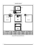
Page 14: ...mension B Dimension C A 12 3 4 24 3 4 14 1 4 B 12 3 4 24 3 4 17 1 2 C 18 1 4 27 1 2 21 B A 12 7 8 3 4 TYP 1 3 4 1 7 8 K O 3 1 4 1 1 4 C 22 1 1 7 8 3 1 2 5 1 2 2 5 8 1 1 8 K O TYP 1 1 4 2 7 8 TOP VIEW...

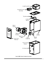
Page 15: ...ount Kit Blower Motor Blower Wheel Blower Housing Transformer Control Board Coil Assembly Outlet Heater Box Lower Front Bracket Blower Door Motor Control Board Rear Bracket Front Joining Bracket Figur...

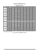
Page 16: ...0 845 780 705 610 530 Corrected ESP1 0 08 0 19 0 31 0 42 0 54 0 65 0 76 Med 1335 1290 1235 1175 1100 1015 925 805 Corrected ESP1 0 10 0 22 0 34 0 46 0 59 0 71 High 1470 1425 1360 1300 1225 1135 1050 9...

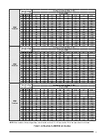
Page 17: ...685 0 1 1 0 1095 1040 995 950 900 850 805 750 1 1 1 0 1155 1105 1060 1010 965 920 870 825 0 0 0 1 1230 1185 1140 1090 1045 1010 965 920 1 0 0 1 1285 1260 1210 1165 1125 1080 1040 1010 0 1 0 1 1330 12...

Page 18: ...0 1 0 650 0 0 1 1 2 TON 1300 0 0 1 1 4 TON 700 0 1 0 0 1350 0 1 0 0 750 0 1 0 1 1400 0 1 0 1 800 0 1 1 0 2 5 TON 1450 0 1 1 0 850 0 1 1 1 1500 0 1 1 1 875 1 0 0 0 1550 1 0 0 0 950 1 0 0 1 1600 1 0 0 1...

Page 19: ...0 1 0 0 700 1 15 1300 1 0 1 0 1 750 1 20 1500 1 0 1 1 0 800 1 25 N A 1 0 1 1 1 850 1 30 N A 1 1 0 0 0 875 1 1 0 0 1 950 1 1 0 1 0 1050 1 1 0 1 1 1150 1 1 1 0 0 1250 1 1 1 0 1 1350 1 1 1 1 0 1400 1 1 1...

Page 20: ...1 7 68 1 50 25 70 020H XX 53 1 103 1 60 110 46 5 43 3 89 8 50 45 90 C 2000CFM None 5 5 15 15 5 5 15 15 005H XX 30 30 35 35 26 7 26 7 30 30 008H XX 44 6 44 6 45 45 39 3 39 3 40 40 010H XX 55 55 60 60 4...

Page 21: ...Thermostat Y1 C Y1 W2 Typical 2 Stage Air Conditioner with Variable Speed Air Handler Typical 2 Stage Heat Pump with Variable Speed Air Handler Y2 Y2 Y2 Y2 OUT W E R Air Conditioner Air Handler Air C...

Page 22: ...age Control Board MB7BM Models Figure 11 Two Stage Control Board MB7EM VM Models LED 1 BLWDTC BLWDTC_R HEAT COOL EAC L 1 L 2 P2 R C G W Y 3A Fuse HEATER P1 C R G Y2 Y O 1W 2W 1Y L LED 1 HEATER P1 L 2...

Page 23: ...W C EXPANSION PORT R RED GREEN TEST PORT BLOWER MOTOR RED INPUTS COOL HEAT FAN SPEED OUTPUTS STATUS LIGHTS 2 3 4 5 6 7 8 OFF ON A B GREEN RED STATUS NOT USED TEST PORT BLOWER MOTOR R C Y1 TWIN DEHUM...

Page 24: ...PLUG HOUSING WHEN HEATER KIT NOT INSTALLED BLACK RED WHITE BROWN BROWN BLACK WHITE RED GRAY YELLOW WHITE GREEN GRAY RED NOTES 1 The blower motor speed tap connection may not be as shown See the Insta...

Page 25: ...2 3 4 5 6 9 PIN HOUSING 9 PIN PLUG 6 PIN PLUG HARNESS BLACK WHITE GRAY RED BLACK RED WHITE BLACK MOTOR 6 PIN PLUG HARNESS WHITE BLACK BLUE GREEN YELLOW ORANGE RED BROWN BLUE GREEN ORANGE RED BROWN YE...

Page 26: ...R BLACK WHITE 6 PIN PLUG 6 PIN PLUG BLACK WHITE BLACK WHITE GRAY RED BLACK HARNESS HARNESS GREEN BROWN RED ORANGE YELLOW GREEN BLUE BROWN RED ORANGE YELLOW GREEN BLUE RED CUT WIRES TO REMOVE PLUG HOU...

Page 27: ...delay W Y AUX HEAT On 5 KW Stage 1 Heat on instantly Cool blower on after 3 second delay 10 KW Stage 1 Heat on instantly Cool blower on after 3 second delay Stage 2 Heat on after 5 seconds delay 15 KW...

Page 28: ...ly Blower off after 15 second delay W1 W2 EHEAT On 5 KW Stage 1 Heat on instantly Heat blower on after 3 second delay 10 KW Stage 1 Heat on instantly Heat blower on after 3 second delay Stage 2 Heat o...

Page 29: ...off instantly Heat blower turns off after 40 second delay W1 W2 Y Y2 AUX HEAT On 5 KW Stage 1 Heat on instantly Cool blower on after 3 second delay 10 KW Stage 1 Heat on instantly Cool blower on afte...

Page 30: ...30...

Page 31: ...31...

Page 32: ...Replaces 7091750 ATTENTION INSTALLERS It is your responsibility to know this product better than your customer This includes being able to install the product according to strict safety guidelines and...

Reviews: