13
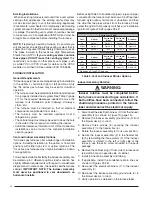
12" Min.
to Maxim
um
Expected Sno
w Le
vel
Typical Both Pipes
36" max.
8" min.
Exhaust V
ent
Right Side Option
Mounting Kit
Faceplate Secured
to Wall with Screws
Typical Both Pipes
Combustion
Air Inlet
Inlet Exhaust
Both Sides
Exhaust Vent
Left Side Option
90°
Elbo
w
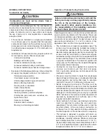
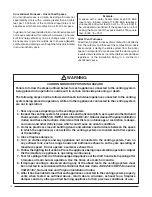
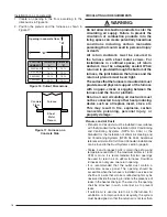
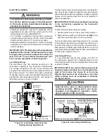
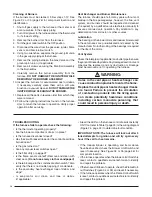
Figure 6. Exhaust and Combustion Air
Pipe Clearances
Vent Freezing Protection
When the vent pipe is exposed to temperatures below
freezing (i.e., when it passes through unheated spaces,
chimneys, etc.) the pipe must be insulated with 1/2 inch
thick sponge rubber insulation, Armafl ex-type insulation
or equivalent. Insulating pipe is important to avoid
condensate icing.
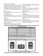
Table 1 lists the maximum length of fl ue pipe that can travel
through an unconditioned space or an exterior space.
The total vent length must not exceed the lengths noted
in Table 15 (page 44).
For Canadian installations please
refer to the Canadian Installation Code (CAN/CGA-B149.1
or 2) and/or local codes.
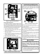
12 in.
12 in.
4 ft.
Note 2
Mechanical
draft vent
terminal
Direct vent
terminal
50,000 Btuh
or less
Forced
Air Inlet
Direct vent
terminal -
more than
50,000 Btuh
Mechanical
draft vent
terminal
Mechanical
draft vent
terminal
Less
than 10 ft.
3 ft.
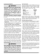
NOTES:
1. All dimensions shown are minimum
requirements.
2. Exterior vent terminations must be located at
least 12 In above the maximum expected snow level.
Note 2
Note 2
9 In.
4ft.
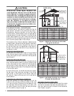
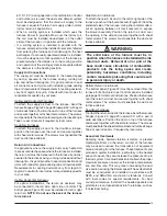
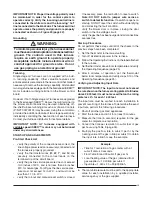
Figure 7 Vent Locations
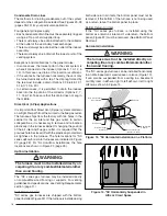
Outside
Wall
Support
Vent Configuration to
Provide 12" Minimum
height above
Snow Level.
1/2"
Armaflex
Insulation or
Equivalent
(if required)
12" Above
Maximum
Expected
Snow Level
12" Min.
19" Max.
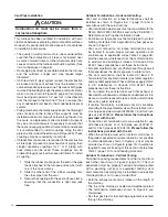
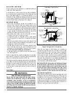
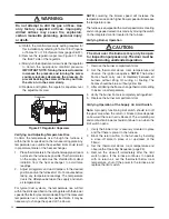
Figure 8. Alternate Horizontal Vent Installation
Winter Design
Temperature
Maximum Flue Pipe Length
in Unconditioned and
Exterior Spaces
Without Insulation
(feet)
With Insulation
(feet)*
20
45
70
0
20
70
-20
10
60
* = Insulation thickness greater than 3/8 inch, based on
an R value of 3.5 (ft x F x hr) / (BTU x in.)
Table 1. Vent Protection
Condensate Disposal
The method for disposing of condensate varies according
to local codes. Consult your local code or authority having
jurisdiction. Neutralizer kit P/N 902377 is available for
use with this furnace.
Please follow the instructions
provided with the kit.
This furnace has multiple options for positioning the
vent pipe as described in the section, Vent and Inducer
Assembly Options. Each of the condensate drain lines
must be J-trapped using fi eld supplied parts. After the
condensate lines are J-trapped, they may be combined
together when routed to the drain.
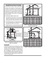
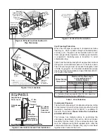
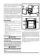
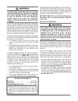
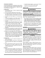
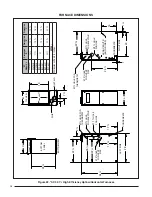
Figure 9. Vertical Vent Termination
Comb
ustion Air
Exhaust V
ent
Plumbing V
ent
Roof Boot
(Typ
. Both Pipes)
8" Min.
36" Max.
90° Elbow
12’ Above Maximum
Expected Snow Level
(Typ. Both pipes)


