13
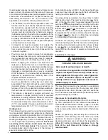
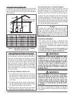
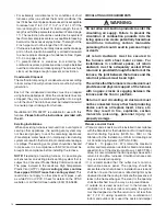
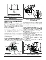
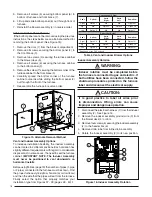
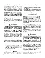
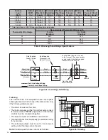
Figure 9. Vertical Vent Termination
Comb
ustion Air
Exhaust V
ent
Plumbing V
ent
Roof Boot
(Typ
. Both Pipes)
8" Min.
36" Max.
90° Elbow
12” Above Maximum
Expected Snow Level
(Typ. Both pipes)
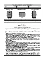
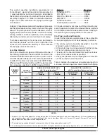
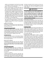
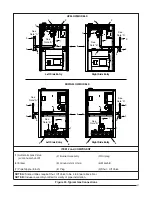
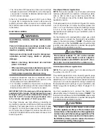
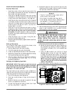
Figure 7 Vent Locations
12 in.
12 in.
4 ft.
Note 2
Mechanical
draft vent
terminal
Direct vent
terminal
50,000 Btuh
or less
Forced
Air Inlet
Direct vent
terminal -
more than
50,000 Btuh
Mechanical
draft vent
terminal
Mechanical
draft vent
terminal
Less
than 10 ft.
3 ft.
NOTES:
1. All dimensions shown are minimum
requirements.
2. Exterior vent terminations must be located at
least 12 In above the maximum expected snow level.
Note 2
Note 2
9 In.
4ft.
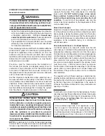
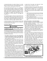
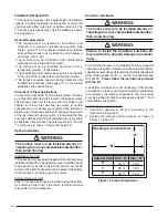
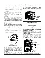
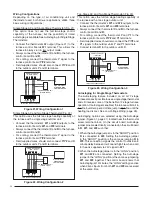
Figure 8. Alternate Horizontal Vent Installation
Support
NOTE: Vent Configuration to Provide 12" Minimum
height above Snow Level.
1/2"
Armaflex
Insulation or
Equivalent
(if required)
12" Above
Maximum
Expected
Snow Level
12" Min.
19" Max.
(See Note)
Outside
Wall
to U.S. installations. In Canada, CSA B149.1, takes
precedence over these instructions.
• Do not install the vent terminal such that exhaust is
directed into window wells, stairwells, under decks
or into alcoves or similar recessed areas, and do not
terminate above any public walkways.
• If venting horizontally, a side wall vent kit is available
according to the pipe diameter size of the installation.
For 2 inch pipe use side wall vent kit #904617, and
for 3 inch pipe use kit #904347.
Please follow the
instructions provided with the kit.
• Concentric vent termination kits are available for use
with these furnaces. For 2 Inch pipe use kit #904177
and for 3 inch pipe use kit # 904176.
Please follow the
instructions provided with the kit.
• When the vent pipe must exit an exterior wall close to
the grade or expected snow level where it is not possible
to obtain clearances shown in Figure 6, a riser may be
provided as shown in Figure 8. Insulation is required
to prevent freezing of this section of pipe. See Table 3
for vent freezing protection.
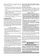
Outdoor Terminations - Vertical Venting
Termination spacing requirements from the roof and from
each other are shown in Figure 9.
The roof penetration
must be properly fl ashed and waterproofed with a plumbing
roof boot or equivalent fl ashing. Vent and combustion air
piping may be installed in an existing chimney which is
not in use provided that:
• Both the exhaust vent and air intake run the length of
the chimney.
• The top of the chimney is sealed and weatherproofed.
• The termination clearances shown in Figure 9 are
maintained.
• No other gas fi red or fuel-burning equipment is vented
through the chimney.
Vent Freezing Protection
• When the vent pipe is exposed to temperatures below
freezing (i.e., when it passes through unheated spaces,
chimneys, etc.) the pipe must be insulated with 1/2 inch
thick sponge rubber insulation, Armafl ex-type insulation
or equivalent. Insulating pipe is important to avoid
condensate icing.
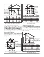
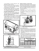
• Table 3 lists the maximum length of fl ue pipe that can
travel through an unconditioned space or an exterior
space. The total vent length must not exceed the lengths
noted in Table 2 (page 11).
For Canadian installations,
please refer to the Canadian Installation Code (CAN/
CGA-B149.1 or 2) and/or local codes.
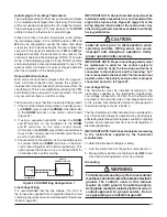
Winter Design
Temperature
Maximum Flue Pipe Length
in Unconditioned and
Exterior Spaces
Without Insulation
(feet)
With Insulation
(feet)*
20
45
70
0
20
70
-20
10
60
* = Insulation thickness greater than 3/8 inch, based on
an R value of 3.5 (ft x F x hr) / (BTU x in.)
Table 3. Vent Protection


