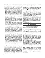
16
Downfl ow Installation
WARNING:
The furnace must not be installed directly on
carpeting, tile, or any combustible material other
than wood fl ooring.
WARNING:
Failure to install the downfl ow sub-base kit
may result in fi re, property damage or personal
injury.
To install the furnace on combustible fl ooring, a special
sub-base is required. Downfl ow sub-base kits are factory
supplied accessories and are listed according to the cabinet
letter of the furnace. For ‘B’, ‘C’, and ‘D’ size cabinets use
Kit #904911.
Please follow the instructions provided
with the kit.
A downfl ow sub-base kit is not necessary if the furnace
is installed on a factory or site-built cased air conditioning
coil. However, the plenum attached to the coil casing
must be installed so that its surfaces are at least 1” from
combustible construction.
Installation on a concrete slab.
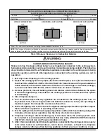
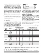
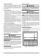
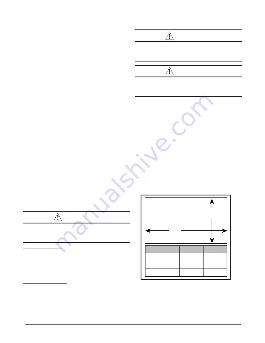
1. Create an opening in the fl oor according to the
dimensions in Figure 10.
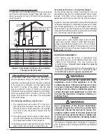
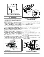
2. Position the plenum and the furnace as shown in
Figure 11 (page 17).
Cabinet Size Dim. “A” Dim. “B”
‘B’
16
⅝
19
¼
‘C’
20
⅛
19
¼
‘D’
23
⅝
19
¼
“A”
“B”
Opening in concrete floor
Figure 10. Cutout Dimensions
FURNACE INSTALLATION
*TC series gas furnaces offer a wide range of installation
options, including installation in the upfl ow or horizontal
positions with either right, left, or upfl ow return air. The
*TL series gas furnaces may only be installed as a down
fl ow application.
General Requirements
• The furnace must be leveled at installation and
attached to a properly installed duct system. See
Table 1 (page 7) for the required clearances needed
to move the furnace to its installation point (hallways,
doorways, stairs, etc).
• The furnace must be installed so that all electrical
components are protected from water.
• The furnace must be installed upstream from a
refrigeration system. (If applicable)
• The cabinet plug must always be used to close the hole
in the side of the furnace when rotating the inducer.
• The furnace requires special venting materials and
installation procedures. See pages 10 -14 for venting
guidelines and specifi cations.
Direct Vent (2-Pipe) Applications
It is important that Direct Vent (2-pipe) systems maintain
an airtight fl ow path from the air inlet to the fl ue gas outlet.
The furnace ships from the factory with two holes in the
cabinet for the air inlet and fl ue gas outlet. In certain
confi gurations, it is necessary to remove and relocate a
plastic cap in the furnace cabinet. If changing the position
of the air inlet and fl ue gas outlet, it is required that the
previous hole be closed off with the plastic cap to maintain
air tightness in the furnace. The hole locations for *TC and
*TL furnaces are shown in Figure 28 (page 34).
Upfl ow Installation
WARNING:
The furnace must not be installed directly on
carpeting, tile, or any combustible material other
than wood fl ooring.
Side Return Air Inlet
*TC series gas furnaces are shipped with the bottom panel
installed (Figure 28). If the upfl ow furnace is installed using
both side return air inlets, the bottom panel must not be
removed. The bottom panel must be in place if the bottom
of the furnace is not being used as a return.
Bottom Return Air Inlet
If the *TC series gas furnace is installed using the bottom
as a return air inlet and 1 side return, the bottom panel
(Figure 28) must be removed.

