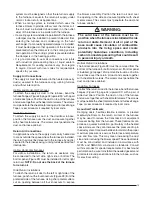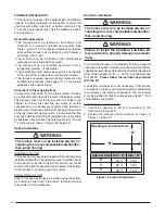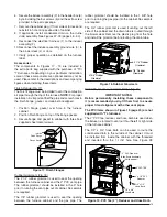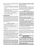
25
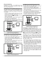
DHUM
R
R
DHUM
HUMIDISTAT
MOTOR
CONTROL BOARD
Figure 24. DHUM Wiring Confi guration 7
Autostaging for Two-Stage Thermostats
The Autostage setting on the furnace control board (Figure
31) is disabled when shipped from the factory. This feature
will be not used when paired with a two-stage thermostat.
The Autostage Jumper (P7) must be kept on the
NONE
setting to allow the thermostat to adjust stages.
Please note that on certain thermostats, even without
the Autostage jumper in the “LONG” position,
W1
and
W2
may be energized at exactly the same time when
a recovery from a set-back begins, the user adjusts the
set point, or the system is powered on. If
W1
and
W2
are
energized at exactly the same time for any reason, the
control will operate in the Autostage “LONG” (12 minute)
mode. If the Autostage jumper is in the “NONE” position
and Autostaging is activated unexpectedly for any of the
reasons listed, it will return to normal, staged operation
after the completion of the heating cycle.
Dehumidifi cation Options
Both motor control boards (Figures 29 & 30, page 41)
have a DHUM connection that causes the system to
increase the amount of humidity that is removed from the
circulating air. This is accomplished by reducing the CFM
and allowing the cooling coil to become colder. This will
only occur when there is a call for cooling.
There are many ways that this can be electrically wired:
1. If the room thermostat incorporates a humidity sensor
and
DHUM
output, connect the
DHUM
on the thermostat
to the
DHUM
terminal on the motor control board
(Figure 24).
2. If using a separate humidistat, connect the
DHUM
and
R
terminals on the humidistat to the
DHUM
and
R
terminals on the motor control board.
In this option, the
DHUM
output of the humidistat must
be set to be normally open and closed when there is
a call for humidifi cation.
3. If a humidistat is not available, it is an acceptable option
to connect the
R
and
DHUM
terminals on the motor
control board together with a fi eld supplied wire. This
option causes the blower to run at a reduced CFM for
10 minutes after a call for cooling.
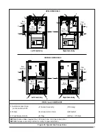
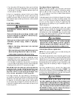
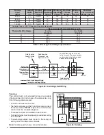
IMPORTANT NOTE: An electrical disconnect must be
installed readily accessible from and located within
sight of the furnace. See Figure 25 (page 26) or the
wiring diagram label inside of the control door. Any
other wiring methods must be acceptable to authority
having jurisdiction.
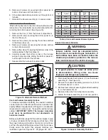
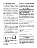
CAUTION:
Label all wires prior to disconnection when
servicing controls. Wiring errors can cause
improper and dangerous operation. Verify
proper operation after servicing.
IMPORTANT NOTE:
Proper line voltage polarity must
be maintained in order for the control system to
operate correctly. Verify the incoming neutral line is
connected to the white wire and the incoming “hot”
line is connected to the black wire. The furnace will not
operate unless the polarity and ground are properly
connected as shown in Figure 25.
Low Voltage Wiring
The thermostat must be installed according to the
instructions supplied by the thermostat manufacturer.
Low voltage connections (24 VAC) from the thermostat
are wired to the terminal strip on the integrated control
in the furnace. Recommended minimum wire gauge for
thermostat wiring is shown in Table 5.
The thermostat must not be installed on an outside wall or
any other location where its operation may be adversely
affected by radiant heat from fi replaces, sunlight, or lighting
fi xtures, and convective heat from warm air registers or
electrical appliances.
IMPORTANT NOTE:
Set the heat anticipator according
to the instructions supplied by the thermostat
manufacturer.
To determine the heat anticipator setting:
1. Add the current draw of the system components; or
2. Measure the current fl ow on the thermostat
R-W
circuit
after the circulating blower motor has started.
Grounding
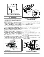
WARNING:
To minimize personal injury, the furnace cabinet
must have an uninterrupted or unbroken electrical
ground. The controls used in this furnace
require an earth ground to operate properly.
Acceptable methods include electrical wire or
conduit approved for ground service. Do not
use gas piping as an electrical ground!
Line Voltage Wiring
It is recommended that the line voltage (115 VAC) to
the furnace be supplied from a dedicated branch circuit
containing the correct fuse or circuit breaker for the furnace
(Table 5, page 26).

