26
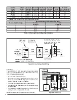
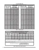
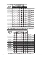
Furnace
Input
(Btuh)
Cabinet
Width
(in.)
Nominal
Electrical
Supply
Maximum
Operating
Voltage
Minimum
Operating
Voltage
Maximum
Furnace
Amperes
Minimum
Wire
Gauge
Maximum
Fuse or Circuit
Breaker Amps**
60,000
17
½
115-60-1
127
103
7.0
14
15
80,000
21
115-60-1
127
103
9.4
14
20
100,000
21
115-60-1
127
103
9.4
14
20
120,000
24
½
115-60-1
127
103
12.5
14
25
** Time-delay fuses or HACR-type circuit breakers are required.
Thermostat Wire Gauge
Recommended Thermostat Wire Length
2 - wire
(Heating)
4 or 5 wire
(Cooling)
24
55 ft.
25 ft.
22
90 ft.
45 ft.
20
140 ft.
70 ft.
18
225 ft.
110 ft.
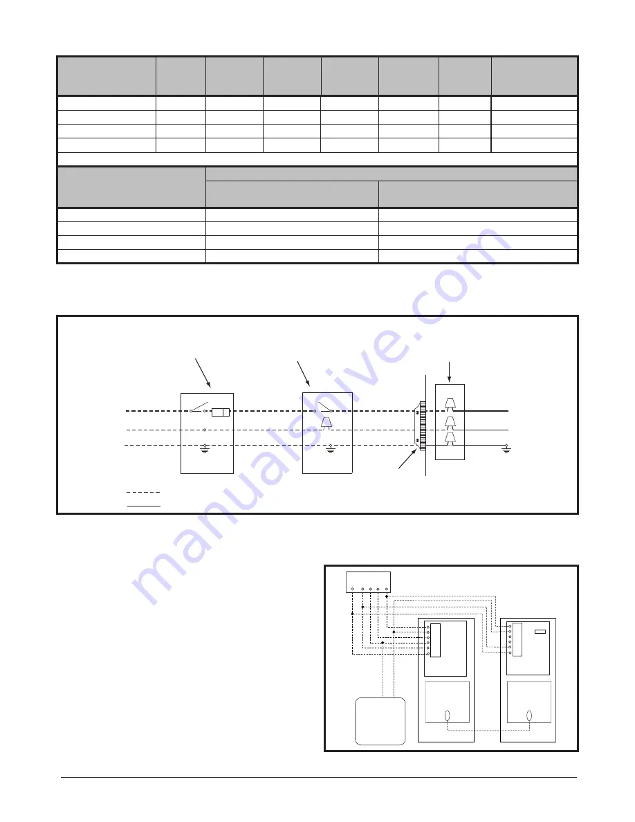
Table 5. Wire Length and Voltage Specifi cations
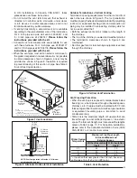
Figure 25. Line Voltage Field Wiring
Field Supplied
Disconnect w/in
Sight of Furnace
Field Supplied
Panel Connector
Field Supplied
Fused Service
Panel
Black (Hot)
White (Neutral)
Green or Bare
(Ground)
Black
White
Black
White
Black
White
Field Line Voltage Wiring
Factory Line Voltage Wiring
Ground
Ground
Junction Box (may be int. or ext.
to the furnace). These connections
can be made in the field supplied
disconnect at the furnace.
Ground
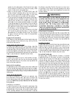
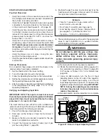
Twinning
The control boards on fi xed speed furnaces are capable
of being twinned to other furnace of the same series, only
if the following criteria are met:
• The circuit boards are the same.
• The thermostat wires and the 1/4 inch thick quick-connect
terminals marked
“TWIN”
(Figure 26) on the furnace
controls must be connected together.
• The fuses must remain installed on each board.
• Twinned furnaces must be properly grounded according
to local codes.
• The autostage jumper must be set to the same pin
setting on both furnace control boards.
Note:
Variable speed furnaces cannot be twinned
.
FURNACE
W1
G
Y
C
R
THERMOSTAT
W1 G Y
R
A/C
FSHE
TWIN TERMINAL
BOARD
UNIT
BOARD
FURNACE
BOARD
FSHE
TWIN TERMINAL
BOARD
FURNACE 1
FURNACE 2
W2
W2
W1
G
Y
C
R
W2
Figure 26. Twinning

