background image

29

airfl ow rate for the capacity. Detailed operation is 
described in the cooling unit installation instruc-
tions and control manual.

Verifying and Adjusting 
Temperature Rise

Verify that the temperature rise through the 
furnace is within the range specifi ed on the 
furnace rating plate.  Temperature rises outside 
the specifi ed range could result in premature 
heat exchanger failure. 

Place temperature measuring device in the return 
and supply air stream as close to the furnace 
as possible. The device on the supply air side 
must be shielded from direct radiation from the 
heat exchanger to avoid false readings. Adjust 
all registers and duct dampers to the desired 
position and run the furnace for fi fteen minutes 
before taking any temperature readings. The 
temperature rise is the difference between the 
supply and return air temperatures.

Verifying Burner Operation

To verify operation of the burners, make sure 
that the blower compartment door is in place 
and that there is power to the furnace. Set 

the thermostat above room temperature and 
observe the ignition sequence. The fl ame can 
be observed  through the small clear window 
on the burner box. The fl ames should be blue, 
without yellow tips. Flames should extend from 
each burner without lifting, curling, or fl oating. 
After verifying ignition, set the thermostat below 
room temperature and verify that the burner fl ame 
extinguishes completely.

Verifying Operation of the Supply 
Air Limit Switch

To verify operation of the supply air  limit switch, 
make sure that the blower door is in place and 
that there is power to the furnace.  Completely 
block the return airfl ow to the furnace by install-
ing a close-off plate in place of or upstream 
of the fi lter(s). Set the thermostat above room 
temperature and verify that the Sequence of 
Operation is as described in these instructions. 
The supply air  limit switch should function to 
turn off the gas valve within approximately fi ve 
minutes. The circulating air and combustion blow-
ers should continue to run when the supply air 
limit switch opens. Remove the close-off plate 
immediately after the supply air limit switch opens. 
If the furnace operates for more than fi ve minutes 
with no return air, set the thermostat below room 

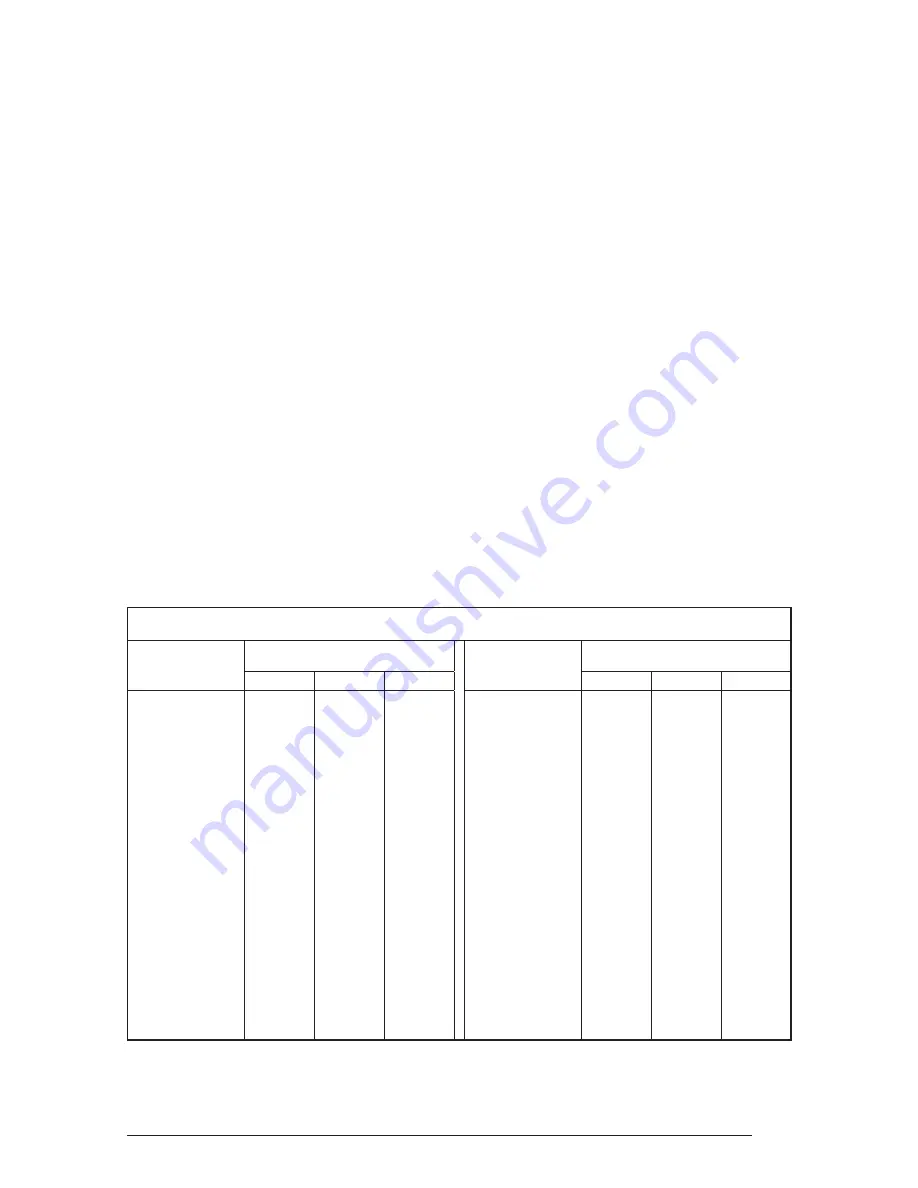
Table 11.  Gas Flow Rate 

GAS FLOW RATE (CUBIC FEET PER HOUR)

TIME FOR

ONE REVOLUTION

(SECONDS)

CUBIC FEET PER REVOLUTION OF 
METER

TIME FOR

ONE REVOLUTION

(SECONDS)

CUBIC FEET PER REVOLUTION OF 
METER

1

5

10

1

5

10

24

150

750

1500

74

49

243

486

26

138

692

1385

76

47

237

474

28

129

643

1286

78

46

231

462

30

120

600

1200

80

45

225

450

32

113

563

1125

82

44

220

439

34

106

529

1059

84

43

214

429

36

100

500

1000

86

42

209

419

38

95

474

947

88

41

205

409

40

90

450

900

90

40

200

400

42

86

429

857

92

39

196

391

44

82

409

818

94

38

191

383

46

78

391

783

96

38

188

375

48

75

375

750

98

37

184

367

50

72

360

720

100

36

180

360

52

69

346

692

102

35

176

353

54

67

333

667

104

35

173

346

56

64

321

643

106

34

170

340

58

62

310

621

108

33

167

333

60

60

300

600

110

33

164

327

62

58

290

581

112

32

161

321

64

56

281

563

114

32

158

316

66

55

273

545

116

31

155

310

68

53

265

529

118

31

153

305

70

51

257

514

120

30

150

300

72

50

250

500

Summary of Contents for TE Series 95

Page 1: ...or maintenance can cause injury or property damage Refer to this manual for assistance For additional information consult a qualified installer service agency or the gas supplier FOR YOUR SAFETY Do n...

Page 2: ...ort 15 Location of Outdoor Terminations 18 Horizontal Venting 18 Vertical Venting 19 Vent Freezing Protection 19 Concentric Vent Termination 20 Drainage of Condensate From Furnace 20 Gas Supply and Pi...

Page 3: ...s A B Combustion Air Vent 3 See Fig 15 for sizes 1 1 2 x 3 1 2 Dia Opening for Gas Connection 3 4 3 4 3 4 22 1 2 Exhaust Vent Combustion Air Inlet 1 1 2 x 3 1 2 Dia Opening for Gas Connection C 2 PVC...

Page 4: ...these instructions 10 The furnace is not to be used for temporary heating of buildings or structures under construction INSTALLATION REQUIREMENTS Requirements and Codes Thisfurnacemustbeinstalledinacc...

Page 5: ...oratory as recognized under 527 CMR 3 A Product approved vent terminal must be used and if applicable a Product approved air intake must be used In stallation shall be in strict compliance with the ma...

Page 6: ...use of unauthorized parts may void the manufacturer s product warranty coverage The 90 upflow furnace can be installed hori zontally in an attic basement crawl space or alcove This furnace can be inst...

Page 7: ...Tee Soft Tubing Looped to Provide a Drain Trap 3 to 2 Reducer Optional Drainage Port is Downward Reducer Bushing Alternative for Horizontal Vent Pressure Switch Pressure Switch Condensate Vinyl Cap Fi...

Page 8: ...be connected to any other heat producing device such as a fireplace insert stove etc CIRCULATING AIR SUPPLY Plenums and air ducts must be installed in ac cordance with the Standard for the Installatio...

Page 9: ...taminated with various household chemicals which can cause severe corrosion in the furnace combus tion system NOTE If the furnace is operated without ad equate air for combustion and ventilation it ma...

Page 10: ...y involves installation in a small room All such installations must have specific provisions for introduction of combustion and ventilation air Codes require that two openings be provided for this one...

Page 11: ...oved for use with these condensing furnaces Table 3 Vent Table table provided in this section applies to the total of vent and combustion air piping for either type of installation These condensing fu...

Page 12: ...Air Duct must be at least 1 sq in per 4 000 Btuh of total input rating Ducts must extend above attic insulation Air Duct must be at least 1 sq in per 4 000 Btuh of total input rating Ventilation Louve...

Page 13: ...ilding 4 Follow the lighting instructions Place the appliance being inspected in operation Adjust thermostat so appliance shall operate continuously 5 Turn on clothes dryers and any other appliance no...

Page 14: ...ion requires breakable connec tions in the piping Note that a maximum of two couplings per pipe are allowed Upflow Furnaces Combustion Air Pipe Exhaust Vent Cabinet 5 Support System on Vertical Rise B...

Page 15: ...longradiuselbow Therefore forour example we have three additional long radius elbowsforwhichwemustaddtoourpiping Each long radius elbow is equivalent to 2 5 feet so we must add 7 5 feet to our vent le...

Page 16: ...000 Btuh 3 kW and 100 00 Btuh 30 kW 6 inches 15 cm for appliances 10 000 Btuh 3 kW 9 inches 23 cm for appliances 10 000 Btuh 3 kW and 50 000 Btuh 15 kW C Clearance to permanently closed window D Vert...

Page 17: ...other appliance 6 inches 15 cm for appliances 10 000 Btuh 3 kW 12 inches 30 cm for appliances 10 000 Btuh 3 kW and 100 00 Btuh 30 kW 36 inches 91 cm for appliances 100 00 Btuh 30 kW 4 feet 1 2 m belo...

Page 18: ...eCanadianFuelGasCodetakes precedence over these instructions Specifi cally allminimumdistancerequirementswith respecttoterminationoftheventpipinglisted below items 1 through 8 The following list is a...

Page 19: ...or pulled through the wall 4 Insure the combustion air inlet pipe for a 2 pipeinstallation hasa90degreetermination elbow as shown in Figures 16 and 17 Note A combustion air intake must be provided wi...

Page 20: ...4 Route the tubing out of the hole located 8 inches up from the bottom furnace The condensate should drain from the plastic collector box location A in Figure 18 as droplets or a small stream If you...

Page 21: ...J Drain Tube Clamp Loosen For Step 1 Retighten for Step 3 Route to floor drain OR Route to condensate pump Keep downward slope Collector Box A Rotate counter clockwise Step 2 Upflow Models the Nationa...

Page 22: ...jury or death Figure 19 Typical Gas Service Connection MANIFOLD PRESSURE ADJUSTMENT Manifold pressures for low and high stages are independently adjustable Adjustment tap locations on the valve are sh...

Page 23: ...500 440 400 370 350 1 1 2 1600 1100 890 760 670 610 560 530 For a Natural Gas Sea Level Heating Value of 800 to 899 Btu cu ft Elevation feet above sea level zero to 1999 2000 to 4999 5000 to 5999 600...

Page 24: ...nace to replace the pressure switch or to utilize LP propane gas must be made by qualified service personnel using factory authorized or approved parts High altitudeapplicationswiththisfurnacecanbefie...

Page 25: ...for the control system to operate correctly Verify that the incoming neutrallineisconnectedtothewhitewireand the incoming hot line is connected to the blackwireinthejunctionbox Thesefurnaces will not...

Page 26: ...ler The thermostat controller must not be installed on an outside wall or any other location where itsoperationmaybeadverselyaffected Adverse effects include radiant loading from fireplaces sunlight o...

Page 27: ...rocedures After all of the above checks have been made 1 Close the disconnect s to provide line volt age to the furnace 2 Setthermostatcontrollerusingtheinstaller s instructions also refer to Table 1...

Page 28: ...alue for instal lation see Table 1 Refer to either Table 6 for natural gas or Table 7 for LP propane gas to verify the manifold pressure setting required for yourparticularinstallation Toadjustthemani...

Page 29: ...f the supply air limit switch make sure that the blower door is in place and that there is power to the furnace Completely block the return airflow to the furnace by install ing a close off plate in p...

Page 30: ...e vent pressure switch reacts to blockage in the vent or combus tion air piping Supply Air Limit Switch The supply air limit switch prevents the air temperature leaving the furnace from exceeding the...

Page 31: ...N TEMP SENSOR SUCTION PRESS SENSOR GREEN BLACK WHITE RED RED EXV 6 WIRE CABLE CABLE WHITE GREEN GREEN BLACK 3 PIN PLUG 6 PIN PLUG WHITE BLACK FURNACE BOARD GREEN RED RED YELLOW GRAY RED YELLOW RED BLU...

Page 32: ...the bearings is required for the life of the motor Condensate Drain Assembly Be sure the condensate lines are free and open i e avoid kinking hoses Also make sure all hose clamps are tight to avoid dr...

Page 33: ...lower Door Switch 10 Vent Safety Switch 11 Low Voltage Transformer 12 Supply Air Limit Switch 3 4 12 18 14 7 9 11 23 5 6 22 10 16 13 15 21 8 17 20 2 1 13 Circulating Air Blower Assembly 14 Induced Dra...

Page 34: ...eignitionfeaturewhich varies the warm up period as follows If igni tion is successful the warm up is reduced by 3 seconds on each subsequent call for heat until ignition failure occurs Upon igni tion...

Page 35: ...ng 1 Is the thermostat operating properly 2 Are the blower compartment door s in place 3 Is the furnace disconnect closed 4 Has the circuit breaker tripped or the control board fuse burned open 5 Is t...

Page 36: ...k tested _______ Gas Line Pressure _____________________ in water column with furnace operating Manifold Pressure ______________________ in water column with furnace operating Is there adequate fresh...

Reviews: