background image

44

Installation

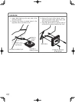
1.  Attach the mounting bracket to the wall.

  The parts to be used vary depending on the 

attachment method.

* Never use electric drivers, impact drivers 

and so forth.

  Tightening  with  excessive  force  may 

result  in  deformation  of  the  mounting 

bracket and/or failures.

Notes on the Installation Location

•  The remote should be installed in an easily 

accessible location.

•  Avoid  installing  in  a  place  where  water 

or  steam  can  come  into  contact  with  the 

controller.

•  Avoid  locations  where  special  chemical 

agents  (e.g.,  benzene,  fatty  and  oily  deter 

gents) are used.

•  Avoid  outdoor  installation,  or  installation  in 

an indoor location where it will be exposed 

to direct sunlight.

Connection of Remote Controller Cord


  White Connector 

  To Remote controller


 Y-shaped terminals    To Water heater

 (two-core)
*  Confirm the connection with the labels at 

both ends of the remote controller cord. 

•  A 26' (8m) cord can be purchased          

separately (Part # RC-CORD26).  

•  The remote controller cord can be extened 

up to 300 ft (90m). by splicing the cord and 

using 18 gauge wire to extend the cord to 

the appropriate length.

(1)

(2)

(2)

(2)

(2)

(1)

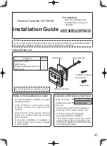
Included Parts List   

(The value in ( ) indicates the quantity.)

Remote Controller 

Mounting

bracket

Raised countersunk 

head wood screw

Wall anchor

Raised countersunk 

head screw

(For junction box 

 installation)

Machine 

screw

<When attaching to a junction box>

• 

Use  the  raised  countersunk  head  screws  to 

attach the mounting bracket to the junction box.

  (In  this  case,  the  wall  anchor  and  raised 

countersunk head wood screws are not used.)

Top

Bottom

Junction box

Mounting bracket

(accessory part)

Raised countersunk 

head screw

 (accessory part)

<When attaching to a wood surface>

• 

Use the raised countersunk head wood screws 

to attach the mounting bracket.

  (In  this  case,  the  wall  anchor  and  raised 

countersunk head screws are not used.)

Top

Bottom

Top

Bottom

<When attaching to a concrete wall surface>

• 

Drill a φ1/4” (φ6mm) hole, approx. 1” (25mm) 

in depth, and hammer in the wall anchor.

  Attach  the  mounting  bracket  using  the  raised 

countersunk head wood screws.

  (In this case, raised countersunk head screws are not used.)

Mounting bracket

(accessory part)

Mounting bracket

(accessory part)

Wall anchor (accessory part)

Raised countersunk 

head wood screw

 (accessory part)

Raised countersunk 

head wood screw

 (accessory part)

Confirm the orientation 

of the mounting bracket.

Confirm the orientation 

of the mounting bracket.

Confirm  the  orientation  of  the 

mounting bracket is correct.

Summary of Contents for GQ-C3257WX-FF US

Page 1: ... the installation instructions Failures and damage caused by erroneous work or work not as instructed in this manual are not covered by the warranty Check that the installation was done properly in accordance with this Installation Manual upon completion After completing installation either place this Installation Manual in a plastic pouch and attach it to the side of the water heater or the insid...

Page 2: ...olation Valves includes pressure relief valve Owner s Guide Installation Manual this document Bird Screen for 4 100mm PVC VT4 PVCS Bird Screen for 3 75mm PVC VT3 PVCS 2 2 PVC Concentric Termination 3 75mm PVC 3CT 1 1 Pipe Cover PC 3S Note Additional vent pieces are available consult the latest product catalogue for details 3 75mm 4 100mm Horizontal Hood Termination PVT HL 2 SV Conversion Kit SV CK...

Page 3: ...n Shutoff Valve Shutoff Valve Hot Water Shutoff Valve Cold Water Distance on sides 2 18 in 50 457mm Size the piping to allow for the maximum flow rates of the units The backflow preventer is put up before it diverges To drain outlet Leave enough clearance around the plumbing to apply insulation It will be necessary to add bends to the piping to ensure that this clearance is available Make this dis...

Page 4: ...a solar pre heater with the quick connect multi system not get to scalding levels Do not use a solar pre heater with the quick connect multi system Precautions for Mobile Home Installation Verify that the gas supply type matches the gas type listed on the rating plate If a gas conversion must be done follow the instructions listed in the gas conversion kit manual If this product will be installed ...

Page 5: ...ulfur ethylene compounds acids are present Using the incorrect voltage may result in fire or cracking Avoid installation in places where dust or debris will accumulate Dust may accumulate and reduce the performance of the unit s fan This can result in incomplete combustion Avoid installation in places where special chemical agents e g hair spray or spray detergent are used Ignition failures and ma...

Page 6: ...code requirements in your area or call 1 855 960 3434 and request instructions Be sure to do Prohibited Prohibited The Commonwealth of Massachusetts The water heater can be used for hot water only and not in a combination of domestic and space heating For Venting Manufacturers Requirements see websites listed below Noritz N Vent www noritz com The water heater is designed for indoor installation o...

Page 7: ...it is recommended to leave 8 200mm or more on either side of the unit 24 600mm or more in front of the unit 3 75mm or more above and below the vent pipe Securing of space for repair inspection 24 600mm or more Distance from the side 12 300mm or more 3 75mm or more 4 100mm or more 3 75mm or more 3 75mm or more 8 200mm or more 8 200mm or more When the indoor air supply If the unit will be installed ...

Page 8: ...r Clearance in accordance with local installation codes and the requirements of the gas supplier Clearance to opposite wall is 24 inches 60 cm 12 in 30 cm 12 in 30 cm 6 in 15 cm for appliances 10 000 Btuh 3kW 12 in 30 cm for appliances 10 000 Btuh 3kW and 100 000 Btuh 30 kW 36 in 91 cm for appliances 100 000 Btuh 30 kW Above a regulator within 3 ft 91 cm horizontally of the vertical center line of...

Page 9: ...anda porch deck or balcony is fully open on a minimum of two sides beneath the floor Clearance in accordance with local installation codes and the requirements of the gas supplier Clearance to opposite wall is 24 inches 60 cm 12 in 30 cm 12 in 30 cm 6 in 15 cm for appliances 10 000 Btuh 3kW 12 in 30 cm for appliances 10 000 Btuh 3kW and 100 000 Btuh 30 kW 36 in 91 cm for appliances 100 000 Btuh 30...

Page 10: ... parts may be damaged and may become highly dangerous Install the unit on a vertical wall and ensure that it is level Locating Screw Holes Mounting Structure When installing with bare hands take caution to not inflict injury Be careful not to hit electrical wiring gas or water piping while drilling holes Item CAUTION Be sure to do Mounting Bracket upper Location of Screw Hole Locating Screw Holes ...

Page 11: ... water into the exhaust accessory on the top of the appliance as illustrated below Or if the vent pipe has already been installed 2 After installing the drain pipe make sure that the area around the appliance is well ventilated open a window or a door if necessary Then operate the unit and verify that condensate is coming out of the drain pipe During normal use of the water heater condensate will ...

Page 12: ...of 149 F 65 C and schedule 40 PVC pipe may be used as the vent material If required by local code use schedule 40 or 80 CPVC Refer to page 14 for additional requirements Make sure the vent system is gas tight and will not leak Support the vent pipe with hangers at regular intervals as specified by these instructions or the instructions of the vent manufacturer All piping must be fully supported Us...

Page 13: ...es to switch the airflow amount 3 6 9 12 15 18 21 24 27 30 33 36 39 42 45 48 51 54 57 60 63 0 90 1 80 2 70 3 60 4 50 5 40 6 30 7 20 8 10 9 00 9 90 10 80 11 70 12 60 13 50 14 40 15 30 16 20 17 10 18 00 18 90 m 1 0 2 3 4 ft Vent length Elbows 1 2 3 4 5 6 7 8 9 10 11 12 13 14 15 16 17 18 19 20 21 Number of pieces 3 6 9 12 15 16 18 21 22 24 27 28 30 33 34 0 90 1 80 2 70 3 60 4 50 4 80 5 40 6 30 6 60 7...

Page 14: ...ng practices must be observed o Squarely cut all pieces of pipe o Remove all burs and debris from joints and fittings o All joints must be properly cleaned primed and cemented Use only cement and primer approved for use with the pipe material as outlined in the above table PVC or CPVC pipe has been approved for use on this appliance with zero clearance to combustibles All piping must be fully supp...

Page 15: ...n the intake and exhaust when installing the vent piping Terminate at least 6 1 8m from the combustion air intake of any appliance and 3 0 9m from any other building opening gas utility meter service regulator etc Enclose exterior vent systems below the roof line to limit condensation and protect against mechanical failure When the vent penetrates a floor or ceiling and is not running in a fire ra...

Page 16: ...ermination may be shortened but not lengthened from its original factory supplied length Terminate at least 12 300mm above grade or above snow line For vertical installation terminate at least 7 2 1m above a public walkway 6 1 8m from the combustion air intake of any appliance and 3 0 9m from any other building opening gas utility meter service regulator etc Slope the horizontal vent 1 4 upwards f...

Page 17: ...ke Exhaust Intake 3 Min WARNING If the distance between the air inlet and exhaust vent terminations is too short the water heater will draw in the exhaust gases through the intake There is a risk of inadequate combustion air for the water heater increasing Carbon Monoxide CO emissions and noise due to vibration Termination elbows must be oriented vertically pointing directly downward Attempts to p...

Page 18: ...t 2 0 6m but not more than 6 1 87m in accordance with the National Fuel Gas Code ANSI Z223 1 NFPA 54 or Natural Gas and Propane Installation Code CSA B149 1 Provide vertical support every 3 0 9m or as required by the vent pipe manufacturer s instructions A short horizontal section is recommended to prevent debris from falling into the water heater When using a horizontal section slope the horizont...

Page 19: ...nute If the unit is installed in a mobile home outdoor air must be supplied The usage of the SV conversion kit is prohibited Supply combustion air to the units as per the National Fuel Gas Code ANSI Z223 1 latest edition and in Canada in accordance with the Natural Gas and Propane Installa tion Code CSA B149 1 latest edition Combustion Air Openings supplying indoor air H H W W Provide adequate com...

Page 20: ... the installer The installer must be professionally trained to do such work and must always follow all local and national codes and regulations Gas line sizing calculations must be performed for every installation Please contact Noritz America at 855 960 3434 if you have any questions or concerns CAUTION Regulators Ensure that all gas regulators used are operating properly and providing gas pressu...

Page 21: ...rding to total btuh demand of the building and length from the meter or regulator so that the following supply pressures are available even at maximum demand WARNING Natural Gas Supply Pressure Min 4 WC Max 10 5 WC LP Gas Supply Pressure Min 8 WC Max 14 WC Reference Tools Sample Calculations The tables and samples below are for reference only The professional sizing and installing the gas line sho...

Page 22: ...Use 50 15m 175 000 Btuh requires 1 Outlet E 25 7 5m Use 30 9m 199 900 Btuh requires 3 4 Section 4 45 13 5m Use 50 15m 355 000 Btuh requires 1 1 4 Natural Gas Meter Noritz Condensing Tankless Gas Water Heater 199 900 Btuh Clothes Dryer 35 000 Btuh Barbecue 50 000 Btuh Gas Range Stove 65 000 Btuh 10 3m 10 3m 10 3m 10 3m 5 1 5m 5 1 5m 5 1 5m 5 1 5m 5 1 5m 5 1 5m Gas Fireplace 25 000 Btuh Section 3 Se...

Page 23: ...at each appliance to verify all appliances are receiving a minimum of 5 WC for NG or 8 WC for LP If all appliances are not receiving the minimum inlet pressure the gas piping system may need to be changed CAUTION Pipe Size Length including fittings 10 20 30 40 50 60 80 100 125 150 175 200 3m 6m 9m 12m 15m 18m 24m 30m 38m 45m 53m 60m 1 2 291 200 160 137 122 110 101 94 89 84 74 67 3 4 608 418 336 28...

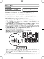
Page 24: ...ot be connected to any heating system or components previously used with a nonpotable water heating appliance When water is required in one part of the system at a higher temperature than in the rest of the system means such as a mixing valve shall be installed to temper the water to reduce the scald hazard Installation and service must be performed by a qualified plumber In the Commonwealth of Ma...

Page 25: ...using abnormal sounds and decreasing the durability of the heat exchanger Freeze Prevention Freezing is prevented within the device automatically unless the outside temperature without wind is below 30 F 35 C When combustion air is supplied from the indoors the room temperature must be greater than 32 F 0 C to prevent freezing and the room inside must not have negative pressure If this model is in...

Page 26: ...form If this water heater will be installed in an application where the supply water is hard the water must be treated with either the Noritz H2Flow or ScaleShield or a water softener Refer to the below tables for suggested treatment and maintenance measures to be taken based on the water hardness level If this water heater will be installed in an application where the supply water is hard Scale B...

Page 27: ...the circulating pump 5 Connect the drain hose H3 to the drain valve V4 6 Pour 1 gallon of 㻯㼍㼘㼏㼕㼡㼙㻘㻌㻸㼕㼙㼑㻌㼍㼚㼐㻌㻾㼡㼟㼠㻌㻾㼑㼙㼛㼢㼍㼘㻌㻼㼞㼛㼐㼡㼏㼠 and 㻝㻌gallon water into the bucket Noritz recommends 㻯㼍㼘㼏㼕㼡㼙㻘㻌㻸㼕㼙㼑㻌㼍㼚㼐㻌㻾㼡㼟㼠㻌㻾㼑㼙㼛㼢㼍㼘㻌㻼㼞㼛㼐㼡㼏㼠 㻌for flushing 7 Place the both drain hoses H2 and H3 into the bucket filled with the flushing solution 8 Open the both drain valves V3 and V4 The water heater must remain connecte...

Page 28: ...e connector marked FLUSH near the Circuit Board 3 Then the code CCC is displayed on the 㻾㼑㼙㼛㼠㼑㻌㻯㼛㼚㼠㼞㼛㼘㼘㼑㼞㻚 4 Turn on the circulating pump to circulate the flushing solution through the water heater for 1 hour at a rate of 1 5 gallons per minute or more 5 The code C60 is displayed on the Remote Controller when the water heater detects the flow of the flushing solution When 1 minute passes the code ...

Page 29: ...s out on the Remote Controller 8 Close the Front Covers 9 Open the gas supply valves and water outlet valves 10 Check for correct operation of the water heaters 855 960 3434 is displayed when the Main Water Heater s blue connector is connected is displayed when the Sub Water Heater s blue connector is connected Main Water Heater Sub Water Heater FLUSH Connect Circuit Board Remote Controller Quick ...

Page 30: ... Long runs or applications where the nearest drain is above the water heater will require the use of a condensate pump Size the pump to allow for a maximum condensate discharge of 2 GPH from the water heater Horizontal runs must be sloped 1 4 per foot towards the drain or condensate pump The condensate will be discharged by gravity force only Make the drain pipe run as short as possible The end of...

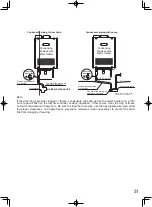
Page 31: ...NCE 1 2 PVC pipe DO NOT ADD ANY VALVES Condensing Tankless Gas Water Heater DO NOT ADD ANY VALVES Condensing Tankless Gas Water Heater Note If the drain line becomes clogged or frozen condensate will back up into the water heater and a 29 error code will flash on the remote controller ceasing operation If this occurs clear the clog or freeze so that condensate can freely flow Be sure to slope the ...

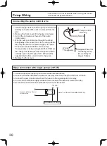
Page 32: ...tion waranty 4 Noritz recommends the use of an Isolation Kit with the installation These kits include an integrated shut off and service valve with unions and a pressure relief valve Notes 1 Noritz recommends the use of an Isolation Kit with the installation These kits include an integrated shut off and service valve with unions and a pressure relief valve 2 Size the pump to provide a maximum of 3...

Page 33: ...heater will not activate resulting in possible freezing damage Do not let the power cord contact the gas piping Tie the redundant power cord outside the water heater Putting the redundant length of cord inside the water heater may cause electrical interference and faulty operation Disconnect Power Electrical Shock Hazard Do not turn power on until electrical wiring is finished Disconnect power bef...

Page 34: ... On Off Button on the remote controller To keep the water heater off let the unit sit for 30 sec to return to the original display This unit can be programmed so that it will default to one of three temperatures if the remote controller is removed 140 F 60 C 130 F 54 C 125 F 52 C To change the default temperature adjust the dip switches as described below The default temperature is 120 F 50 C 1 Di...

Page 35: ...te controller cord to the terminal block 5 Replace the terminal block cover and install the screw previously removed in step 3 6 Reconnect electrical power to the water heater External connection terminal block Wiring throughway Remote controller cord Changing Other Features Adjusting the Temperature Display Note The setting must be done within the first 10 minutes of connecting electrical power t...

Page 36: ...om a wall circuit to the pump 5 Replace the front cover Pump Wiring This feature is not available when using the Quick Connect Multi System feature Relay connection with larger pumps 85 W 1 Locate and prepare the pump control wires as described above 2 Choose a suitable installation location for the relay where it will be protected from moisture 3 Connect the pump control wires from the heater to ...

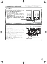
Page 37: ...k Connect Cord Clamp Ground wire Connector Connector Connecting Quick Connect Cord 2 Caution For Quick Connect Multi System Installation use part QC 2 only sold separately Quick Connect Cord 2 Quick Connect Cord 2 tag A B 1 Red 2 Black 3 White 4 Green 5 Blue 6 Blue 1 Red 2 Black 3 White 4 Green 5 Blue 6 Blue 1 Red 2 Black 3 White 4 Green 5 Blue 6 Blue 1 White 2 Green 3 Red 4 Black 5 Blue 6 Blue Th...

Page 38: ...ear normal the burner may need to be cleaned by qualified service technician Do not obstruct the flow of combustion and ventilation air The pressure relief valve must be operated once a year to ensure that it is functioning properly and there is no obstruction Turn the power off to the unit before opening the relief valve and make sure that water draining out of the valve will not cause any damage...

Page 39: ...trol manual valve clockwise to the off position Should overheating occur or the gas supply fail to shut off turn off the manual control valve to the appliance Handling after trial operation If the unit will not be used immediately close off all gas and water shutoff valves drain all of the water out of the unit and the plumbing system to prevent the unit and system from freezing and bleed the gas ...

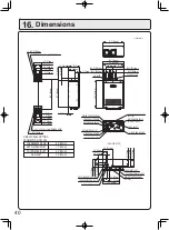
Page 40: ...D WATER INLET HOT WATER OUTLET CONDENSATE DRAIN FROM BOTTOM OF CASE HEIGHT OF EACH FITTING 6 7 170mm 5 5 140mm 3 9 100mm 2 8 70mm 1 4 36mm 0 4 10mm 4 Ø0 5 Ø13mm 6 0 24 x 0 4 6 x 10mm OBLONG HOLE 1 6 40mm 5 3 135mm 6 1 155mm 4 3 109mm 2 4 60mm 6 7 171mm 7 0 177mm 26 2 665mm 23 1 586mm 24 2 615mm 2 4 61mm 0 4 10mm 9 4 240mm 5 5 140mm 1 1 28mm Ø4 5 Ø114mm Ø3 5 Ø89mm 17 7 450mm 18 3 464mm 17 6 448mm 5...

Page 41: ...s on the Installation Location The remote should be installed in an easily accessible location Avoid installing in a place where water or steam can come into contact with the controller Avoid locations where special chemical agents e g benzene fatty and oily deter gents are used Avoid outdoor installation or installation in an indoor location where it will be exposed to direct sunlight Connection ...

Page 42: ...cord Phillips Roundhead Wood Screw Wall Anchor 3 Remove the cover of the remote control mark the location of the screw holes and drill holes for the wall anchors 4 Insert the wall anchors screw the remote control to the wall and replace the cover Remote Controller Cord Wall Packing take off the paper Remote Control Wires Rear Side of Remote Controller ...

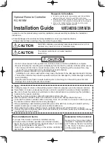
Page 43: ...er In order to use this product safely read this installation manual carefully and follow the installation instructions Potential dangers from accidents during installation and use are described below Closely observe these warnings they are critical to your safety The remote controller is not water resistant Keep it dry CAUTION Do not connect power to the system unit until the remote controller in...

Page 44: ...t The value in indicates the quantity Remote Controller Mounting bracket Raised countersunk head wood screw Wall anchor Raised countersunk head screw For junction box installation Machine screw When attaching to a junction box Use the raised countersunk head screws to attach the mounting bracket to the junction box In this case the wall anchor and raised countersunk head wood screws are not used T...

Page 45: ...of the remote controller and the frame pull the entire decorative frame forward while pressing the sections indicated where the fingers are in the figure below If it does not come off insert a flat head driver into the notch at the bottom of the decorative frame and slightly twist it to remove due caution is required not to scratch the remote controller decorative frame or the wall in doing so Cli...

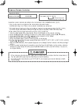
Page 46: ...R Button the Misc settings screen appears on the display 4 Select Max set Temp using the Buttons 5 Press the ENTER Button 120 F 50 C appears on the display 6 Set the upper limit of the hot water supply temperature to 125 F 130 F 135 F or 140 F 55 C or 60 C using the Buttons 7 Press the ENTER Button Set complete appears on the display and then returns to the Misc settings screen 8 To put the water ...

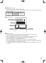
Page 47: ... cover select Initial settings using the Buttons 4 Press the ENTER button the Initial settings screen appears on the display 5 Select F gal C L using the Buttons 6 Press the ENTER Button and select either F gal or C L using the Buttons 7 Press the ENTER Button Set complete Please wait appears on the display for 5seconds and then the Initial settings screen appears on the display 8 To confirm the s...

Reviews: