CP6, CP7, or CP8: Series Programmable Controller
Version 1.0
Page 21
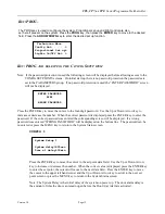
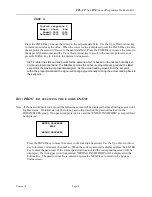
temperature. When the compressor type is set to
HI / LO
. The system runs only one
compressor at a time and switches between the two units, as the room temperature
reaches the Switch Temp set point. When
FAN CONT.
has been selected the fan will run
continuously. If
FAN AT DEMAND
has been selected, the fan will only operate when it is
needed.
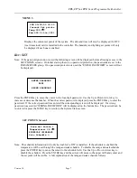
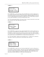
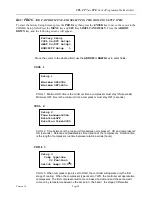
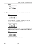
COOL 4
COOL 4: Cooling stage 1 offsets. The cooling relay will energize when the room
temperature reaches the Set Point + On offset. The cooling relay will de-energize when
the room temperature reaches the Set Point + Off offset.
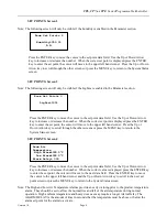
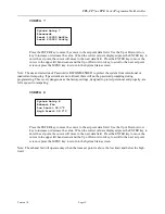
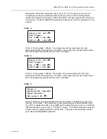
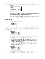
COOL 5
COOL 5: Cooling stage 2 offsets. The cooling 2 relay will energize when the room
temperature reaches the Set Point + On offset. The cooling relay will de-energize when
the room temperature reaches the Set Point + Off offset.
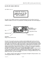
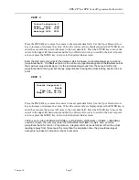
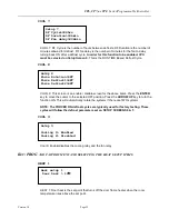
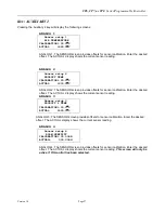
COOL 6
COOL 6: Defrost is an enable/disable switch for the defrost. The defrost can be set to
“Electric” or “Hot Gas”. The compressor is shut down during an “Electric Defrost Cycle”.
If no RTC is installed the USE is set to
SYS
and the defrost cycles will occur on the RUN
TIME and will have to be set up in “
CONFIG 4
” screen. The thermostat will be using the
duration time as a safety (maximum defrost time). The system will not initiate a defrost
cycle above the
Set point
temperature.
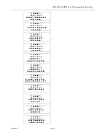
Setup 4 SP: 004.0
C
Cool Stage 1
On> 0.2
C = 004.2
C
Off>-0.2
C = 003.8
C
Setup 5 SP: 004.0
C
Cool Stage 2
On> 1.0
C = 004.2
C
Off>0.0
C = 003.8
C
Setup 6
Defrost>Off Use>SYS
Type> Electric
Set point> 02.0
C

