background image


CP6, CP7, or CP8: Series Programmable Controller


Version 1.0


Page 28 

K

EY

:


I/O


Pressing the I/O key will display the following screens:


NOTE: The following screens and parameters are for MANUAL
 testing of the devices listed. 


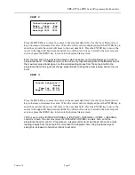
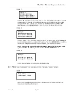
MAN 1 

Manual control 1 
           MODE   POS 
      Fan 1>AUTO >OFF 
  Defrost 1>AUTO >OFF


MAN 1: This screen is used for testing each device manually.  Set the MODE type as 

HAND

, (manual position) and then the 

POS

 will indicate the desired position of the device. 


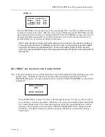
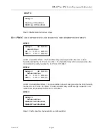
MAN 2 

Manual control 2 
           MODE   POS 
     Cool 1>AUTO >OFF 
     Heat 1>AUTO >OFF


MAN 2: This screen is used for testing each device manually.  Set the MODE type as 
HAND, (manual position) and then the POS will indicate the desired position of the 
device. 


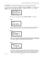
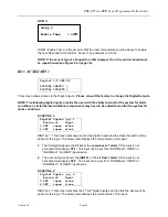
MAN 3 

Manual control 3 
           MODE   POS 
    Humid 1>AUTO >OFF 
  Dehumid 1>AUTO >OFF


MAN 3: This screen is used for testing each device manually.  Set the MODE type as 
HAND, (manual position) and then the POS will indicate the desired position of the device. 


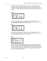
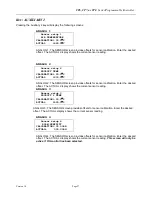
MAN 4 

Manual control 4 
           MODE   POS 
      Fan 2>AUTO >OFF 
  Defrost 2>AUTO >OFF


MAN 4: This screen is used for testing each device manually.  Set the MODE type as 
HAND, (manual position) and then the POS will indicate the desired position of the device. 
NOTE:

 This screen will only be present when 

COOL 1

 or 

HEAT 1 

is enabled. 


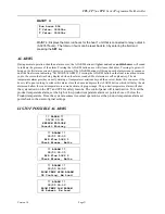
MAN 5 

Manual control 5 
           MODE   POS 
  T Valve 1>AUTO >000% 
  T Valve 2>AUTO >000%


MAN 5: This screen is used for testing each device manually.  Set the MODE type as 
HAND, (manual position) and then the POS will indicate the desired position of the device. 


Summary of Contents for CP6 Series

Page 1: ...7 Alarm Set Points 8 Ramp Soak Programing 10 High level configuration 12 Proportional Set up 16 Lighting Set up 18 Cooling Set up 20 Heat Set up 22 Humidity Set up 24 Digital Inputs 26 Sensor calibrat...

Page 2: ...to an existing building automation system monitor the sensors compressors and heaters for failure On a sensor failure the applicable systems are disabled On a compressor failure by low or high pressur...

Page 3: ...ith LED s Returns you to the main display from anywhere in the program Displays the maintenance information of each device working hours Allows you to access the displays concerning the printer option...

Page 4: ...and humidity control The green LED lit behind the button indicates that the unit is ON WARNING DISCONNECT ALL SYSTEM POWER BEFORE SERVICING ANY EQUIPMENT 2 Alarm by pressing this button you can displa...

Page 5: ...t is connected to the control board by a 6 wire standard phone cord of up to 1 000 feet in length NOTE A short special phone cord is supplied with the controller Connect a standard 6 wire phone cord e...

Page 6: ...ll only be displayed if the humidifier or dehumidifier control has been enabled The lower line displays a second product temperature Note Product 2 temperature will only be displayed if an additional...

Page 7: ...isplayed press the ENTER key to enter the password If the correct password was entered the corresponding screen will be displayed If a wrong password was entered WRONG PASSWORD will be displayed on th...

Page 8: ...s the Up or Down Arrow key to scroll through the other screens or press the MENU key to return to the System Status screen SET POINTS Screen 4 Press the ENTER key to move the cursor to the set point d...

Page 9: ...he set point the cursor will move to the next data field Press the ENTER key to move the cursor to the upper left hand corner and the Up or Down Arrow key to scroll to the next set point screen or pre...

Page 10: ...e temperature set point field Use the Up or Down arrow key to enter the desired temperature set point Press the ENT key and the cursor will move to the humidity set point field if activated Use the Up...

Page 11: ...12 00 Sunday The temperature set point will remain at 4 0 C until the schedule repeats Monday at 06 00 It is recommended to fill out the Ramp and Soak worksheet on page 47 of this manual before progr...

Page 12: ...NTER key to enter the password If the correct password was entered the corresponding screen will be displayed If a wrong password was entered WRONG PASSWORD will be displayed on the bottom line The pa...

Page 13: ...ENTER key to enter the set point the cursor will move to the next data field Press the ENTER key to move the cursor to the upper left hand corner and the Up or Down Arrow key to scroll to the next set...

Page 14: ...int screen or press the MENU key to return to the System Status screen Note If the user changes temperature units all set points and bands must be verified in terms of the new unit If the parameters h...

Page 15: ...there will not be password prompting during programming This is very dangerous as the factory settings designed to protect personnel and property are left exposed to tampering CONFIG 8 Press the ENTER...

Page 16: ...ntered or press the MENU key to return to the System Status screen PROP 1 Press the ENTER key to move the cursor to the set point data field Use the Up or Down Arrow key to increase or decrease the va...

Page 17: ...roportionally to bring the actual reading back to the set point PROP 3 Press the ENTER key to move the cursor to the set point data field Use the Up or Down Arrow key to increase or decrease the value...

Page 18: ...proportional band the signal will change proportionally to bring the actual reading back to the set point KEY PROG AND SELECTING THE LIGHTS ON OFF Note If the password protection is used the following...

Page 19: ...value is displayed press the ENTER key to enter the set point the cursor will move to the next data field Press the ENTER key to move the cursor to the upper left hand corner and the Up or Down Arrow...

Page 20: ...OOL 2 COOL 2 Time between is the minimum time between compressor 1 ON and compressor 2 ON seconds Rotation enables disables time rotation of the compressors Rotation time is the length of compressor r...

Page 21: ...sets The cooling 2 relay will energize when the room temperature reaches the Set Point On offset The cooling relay will de energize when the room temperature reaches the Set Point Off offset COOL 6 CO...

Page 22: ...OFF position Press the ARROW UP key to turn the function ON This will automatically rotate the systems if there are TWO systems NOTE The FORCED ON defrost cycles are typically used for factory testin...

Page 23: ...T 4 HEAT 4 Heating stage 3 offsets The heat 3 relay will energize when the room temperature reaches the Set Point On offset The heat 3 relay will de energize when the room temperature reaches the Set...

Page 24: ...elative humidity reaches the Set Point Off offset HUM 2 HUM 2 De Humidifier offsets The de humidifier relay will energize when the room humidity reaches the Set Point On offset The de humidifier relay...

Page 25: ...m conditions DIGITAL 1 Digital Inputs pg 1 Active if Input 1 OFF open close 2 OFF open close DIGITAL 1 This screen activates the first two digital inputs and the state the alarm will be active for the...

Page 26: ...this input is not activated it will display OFF The input can be set for a NORMALLY OPEN or NORMALLY CLOSED input device DIGITAL 4 Digital Inputs pg 4 Active if Input 7 OFF open close 8 OFF open clos...

Page 27: ...OG 2 The SENSOR screen provides offsets for sensor calibration Enter the desired offset The ACTUAL display shows the current sensor reading ANALOG 3 Sensor setup 3 PRODUCT 2 TEMP CALIBRATION 00 0 C AC...

Page 28: ...POS will indicate the desired position of the device MAN 3 Manual control 3 MODE POS Humid 1 AUTO OFF Dehumid 1 AUTO OFF MAN 3 This screen is used for testing each device manually Set the MODE type as...

Page 29: ...00 Lights 4 AUTO 000 MAN 8 This screen is used for testing each device manually Set the MODE type as HAND manual position and then the POS will indicate the desired position of the device NOTE The lig...

Page 30: ...1 that are connected to relay outputs 0 32767hours The total run hours can be reset to 0 by entering the field and pressing the SET key There will be a duplicate screen displayed if two systems have b...

Page 31: ...Most alarms are self explanatory The air temperature alarm provides an early warning of temperature variations beyond the user set limits this can occur if the door is left open too long to silence t...

Page 32: ...IDITY HIGH ALARM ALARM 00 00 00 00 ROOM HUMIDITY LOW ALARM ALARM 00 00 00 00 COMPRESSOR 1 HIGH LOW PRESSURE ALARM 00 00 00 00 COMPRESSOR 2 HIGH LOW PRESSURE ALARM 00 00 00 00 HI LIMIT HUMIDISTAT WATCH...

Page 33: ...rammable Controller Version 1 0 Page 33 ALARM 00 00 00 00 PRODUCT TEMPERATURE SENSOR ALARM ALARM 00 00 00 00 RETURN HUMIDITY SENSOR FAILURE ALARM 00 00 00 00 POWER RESTART NO MORE ALARMS Key ENTER to...

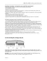
Page 34: ...est two holes in the upper rear of the control panel enclosure Mark the location of these two holes on the walk in panel This will locate the screw location for the keyhole slots 3 Move the control pa...

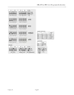
Page 35: ...ts 8 digital inputs 24Vac Vdc 9 digital inputs 230Vac or 24Vac Vdc 10 connector with Vref for power to 5V ratiometric probes and Vterm for power to ARIA terminal 11 connector for all the standard pCO...

Page 36: ...safety transformer rated to at least 40VA and with a 24Vac output To supply more than one controller with the same transformer its rated power must be n x 40VA where n is the number of controllers su...

Page 37: ...ctive load and power cables to avoid possible electromagnetic disturbance Never use the same channelling including that used for the electrical cables for the power cables and probe cables Avoid the p...

Page 38: ...CP6 CP7 or CP8 Series Programmable Controller Version 1 0 Page 38...

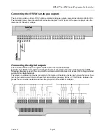
Page 39: ...from the inductive load and power cables to avoid possible electromagnetic disturbance 230Vac digital inputs The following figure represents one of the more common connection diagrams for the 115 230...

Page 40: ...roller features up to 13 digital outputs with electromechanical relays For ease of installation the common terminals of some of the relays have been grouped together If the following diagram is used t...

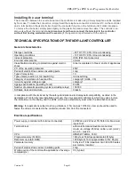
Page 41: ...1C Type of disconnection or microswitching microswitching Category of resistance to heat and fire category D UL94 V0 Immunity against voltage surges category 1 Ageing specifications operating hours 80...

Page 42: ...closed in DC analogue input B5 B6 ms 250 this value needs to be added to the processing time of the application software WARNING for the power supply of any active probes 24Vdc available at the Vdc t...

Page 43: ...tection on both contacts Commutable power and related electrical parameters 2000VA 250Vac 8A resistive 2A FLA 12A LRA according to UL873 30 000 cycles 2A resistive 2A inductive cos 0 4 2 2 A according...

Page 44: ...aching to plastic case Terminal electrical specifications Power supply 21 30Vdc from the power board via telephone cable CPU 80C52 8MHz Operating conditions 0T50 0 50 C 32 122 F 90 rH non condensing S...

Page 45: ...07 Main board Small Board P N 113403 Small Board Connectors P N 113404 Medium Board P N 113405 Medium Board Connectors P N 113406 Connection lead Connection lead terminal unit main board L 0 8m P N 10...

Page 46: ...CP6 CP7 or CP8 Series Programmable Controller Version 1 0 Page 46 Ramp and Soak Worksheet Program Daily Weekly Time Temp Humidity Lights Ramp Hold 1 2 3 4 5 6 7 8 9 10 11 12 13 14 15 16 17 18 19 20 21...

Reviews: