CP6, CP7, or CP8: Series Programmable Controller
Version 1.0
Page 36
I
NSTALLATION
Anchoring the Control
The controller should be installed on a DIN rail. To fasten the unit, press it lightly against the rail. The rear
tabs will click into place, locking the unit to the rail. Removing the unit is just as simple, using a screwdriver
through the release slot to lever and lift the tabs. The tabs are kept in the locked position by springs.
Power supply
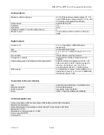
The controller can be powered at: 22/38Vdc and 24Vac ±15%, 50/60 Hz, with a maximum power input
Pmax= 13W. For alternating current power supplies, during installation use a Class II safety transformer,
rated to at least 40VA and with a 24Vac output. To supply more than one controller with the same
transformer, its rated power must be n x 40VA, where n is the number of controllers supplied by the
transformer, independently of the version of the controller. The power supply to the controller/controllers and
the terminal/terminals must be separated from the power supply to the other electrical
devices (power contactors and other electromechanical components), inside the electrical panel. If the
transformer secondary is earthed, make sure that the ground wire is connected to terminal G0.When
powering a series of boards connected in a plan
network, make sure that the G and G0 connections are
correct (G0 must be same for all the boards).
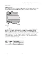
The table below summarises the possible status of the power LED.

