8.5.1
Adjustments procedure
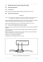
The Clearance transmitter shall be switched off during steps a) through e) below.
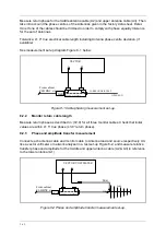
1. Connect the Field Test Set to the CL output of the MCU. Insert the 90° stub in the SBO out-
put of the Transmitter Cabinet. In the Antenna Distribution Unit (ADU), disconnect SBO to
Lower antenna by using the SBO-L link. Terminate open ends. Adjust Upper antenna
phaser PH1 in MCU to give 0% DDM.
2. Reconnect SBO to Lower antenna. Remove the 90° stub. Adjust CL attenuator AT1 in
MCU to give 0 % DDM.
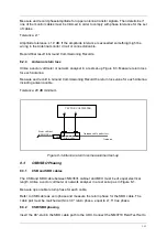
3. Connect the Field Test Set to the DS output of the MCU. Insert the 90° stub in the SBO out-
put of the Transmitter Cabinet. Adjust Middle antenna phaser PH2 in MCU to give 0%
DDM.
4. Remove the 90° stub. Adjust DS attenuator AT2 in MCU to give 8.75% DDM (75
µ
A), 150
Hz dominance.
5. Connect the Field Test Set to the CLR output of the MCU. Adjust phaser PH3 in MCU to
maximum DDM (150 Hz dominance).
6. Turn on CLR transmitter. Check that sufficient 150Hz dominance remains.
8.6
Location of near field antenna position
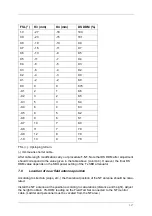
According to site data (slope, etc.,) the theoretical position of the NF antenna should be calcu-
lated.
Install the NF antenna at the position according to calculations (distance and height). Adjust
the height to 0 DDM reading on the Field Test Set connected to the NF monitor cable. (Ladder
and personnel must be removed from the NF area.)
8.6.1
Near Field Monitor Position Search
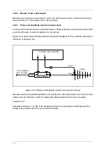
A de-phasing test procedure of upper antenna (A3) can be carried out in order to search for
the optimum monitor position.
A N-type adapter (-27°) (made from a male-male and female-female adapter put together) is
inserted in the lower antenna feed (A1) and middle antenna feed (A2). This is equivalent to
advance (+) phase of the upper antenna.
Retard (-) phase is introduced by inserting the adapter in upper antenna feed A3 only.
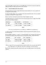
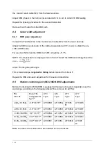
The DDM readings and correlation of the monitor antenna signal to the CL integral from MCU
(far field) should theoretically be:
Dephasing
Near Field (NF)
Far field (CL)
27° retard
-12µA/-1.4% DDM
-11µA/-1.3% DDM
27° advance
-9µA/-1.1% DDM
-11µA/-1.3% DDM
Summary of Contents for NM 7000 Series
Page 7: ...1250 5 167580 17 1 1 6 67 0 167 7 21 200 66 21 1 1 22 1DYLD YLDWLRQ 6 ...
Page 11: ...1250 5 167580 17 1 1 6 67 0 167 7 21 200 66 21 1 1 22 1DYLD YLDWLRQ 6 Figure 2 3 ...
Page 13: ...1250 5 167580 17 1 1 6 67 0 167 7 21 200 66 21 1 1 22 1DYLD YLDWLRQ 6 ...
Page 19: ...1250 5 167580 17 1 1 6 67 0 167 7 21 200 66 21 1 1 22 1DYLD YLDWLRQ 6 ...
Page 21: ...1250 5 167580 17 1 1 6 67 0 167 7 21 200 66 21 1 1 22 1DYLD YLDWLRQ 6 ...
Page 23: ...1250 5 167580 17 1 1 6 67 0 167 7 21 200 66 21 1 1 22 1DYLD YLDWLRQ 6 ...
Page 25: ...1250 5 167580 17 1 1 6 67 0 167 7 21 200 66 21 1 1 22 1DYLD YLDWLRQ 6 ...
Page 27: ...1250 5 167580 17 1 1 6 67 0 167 7 21 200 66 21 1 1 22 1DYLD YLDWLRQ 6 ...
Page 31: ...1250 5 167580 17 1 1 6 67 0 167 7 21 200 66 21 1 1 22 1DYLD YLDWLRQ 6 ...
Page 45: ...1250 5 167580 17 1 1 6 67 0 167 7 21 200 66 21 1 1 22 1DYLD YLDWLRQ 6 ...
Page 55: ...1250 5 167580 17 1 1 6 67 0 167 7 21 200 66 21 1 1 22 1DYLD YLDWLRQ 6 ...
Page 65: ... ...
Page 81: ... ...
Page 111: ... ...
Page 129: ... ...
Page 132: ... ...
Page 134: ...1250 5 167580 17 1 1 6 67 0 167 7 21 200 66 21 1 1 22 1DYLD YLDWLRQ 6 ...
Page 150: ...1250 5 167580 17 1 1 6 67 0 167 7 21 200 66 21 1 1 22 1DYLD YLDWLRQ 6 ...
Page 158: ...1250 5 167580 17 1 1 6 67 0 167 7 21 200 66 21 1 1 22 1DYLD YLDWLRQ 6 ...

