9
,167$//$7,21 &200,66,21,1*+$1'%22.
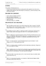
GENERAL
The purpose of this document is to
•
Ensure that all operating functions are working before the equipment is put into service.
•
Establish useful reference data and settings for comparisons to routine maintenance data
and trouble shooting.
REQUIRED TEST EQUIPMENT
•
Vector voltmeter or Network Analyser
•
General purpose Oscilloscope
•
Frequency Counter, 30 Hz to 350 MHz
•
Digital Multimeter
•
Directional Coupler, 75 - 350 MHz
DESCRIPTION OF TEST PROCEDURE
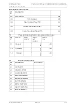
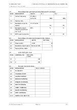
1.1
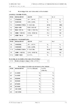
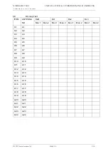
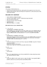
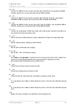
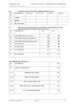
Insert a 30 dB directional coupler in the antenna cable at the output connector. Turn OFF
the modulation and connect a frequency counter to the detector output. Record the RF fre-
quency. Switch to Tx 2 and repeat the procedure.
1.2
Set modulation to ‘keyed’. With Tx 1 switched on and the oscilloscope connected to the
detector output, observe the keying code. Switch to Tx 2 and repeat the procedure.
1.3
With Tx 1 switched on, connect a frequency counter to TP 704 on TX1373A. Set Tx 1 mod-
ulation to ‘CONTINUOUS MODULATION’ and read Tx 1 modulation frequency. Change to
transmitter 2 and set Tx 2 modulation to ‘CONTINUOUS MODULATION’. Record Tx 2
modulation frequency.
1.4
Set Tx 1 in normal operation, read the Modulation Depth value from Monitor 1 and 2.
Change over to Tx 2 and repeat the procedure.
1.5
With Tx 1 in normal operation, read RF Power from the Maintenance Monitor. Change over
to Tx 2 and repeat the reading.
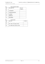
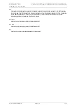
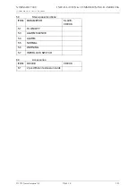
2.1
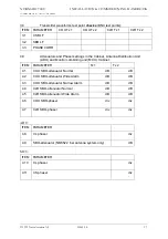
Insert a 3 dB attenuator to the output. Set the transmitter to keyed operation with the output
power 3 dB below normal level. Adjust the RF ALARM LOWER LIMIT until the alarm lamp
is lit. Remove the 3 dB attenuator. The alarm lamp shall extinguish.
2.2
Set the transmitter to keyed operation. Set Tx in test mode and reduce modulation depth
until the alarm lamp is lit.
2.3
With Tx 1 in normal keyed operation, set modulation to ‘CONTINUOUS MODULATION’
and observe that the alarm lamp is lit.
Summary of Contents for NM 7000 Series
Page 7: ...1250 5 167580 17 1 1 6 67 0 167 7 21 200 66 21 1 1 22 1DYLD YLDWLRQ 6 ...
Page 11: ...1250 5 167580 17 1 1 6 67 0 167 7 21 200 66 21 1 1 22 1DYLD YLDWLRQ 6 Figure 2 3 ...
Page 13: ...1250 5 167580 17 1 1 6 67 0 167 7 21 200 66 21 1 1 22 1DYLD YLDWLRQ 6 ...
Page 19: ...1250 5 167580 17 1 1 6 67 0 167 7 21 200 66 21 1 1 22 1DYLD YLDWLRQ 6 ...
Page 21: ...1250 5 167580 17 1 1 6 67 0 167 7 21 200 66 21 1 1 22 1DYLD YLDWLRQ 6 ...
Page 23: ...1250 5 167580 17 1 1 6 67 0 167 7 21 200 66 21 1 1 22 1DYLD YLDWLRQ 6 ...
Page 25: ...1250 5 167580 17 1 1 6 67 0 167 7 21 200 66 21 1 1 22 1DYLD YLDWLRQ 6 ...
Page 27: ...1250 5 167580 17 1 1 6 67 0 167 7 21 200 66 21 1 1 22 1DYLD YLDWLRQ 6 ...
Page 31: ...1250 5 167580 17 1 1 6 67 0 167 7 21 200 66 21 1 1 22 1DYLD YLDWLRQ 6 ...
Page 45: ...1250 5 167580 17 1 1 6 67 0 167 7 21 200 66 21 1 1 22 1DYLD YLDWLRQ 6 ...
Page 55: ...1250 5 167580 17 1 1 6 67 0 167 7 21 200 66 21 1 1 22 1DYLD YLDWLRQ 6 ...
Page 65: ... ...
Page 81: ... ...
Page 111: ... ...
Page 129: ... ...
Page 132: ... ...
Page 134: ...1250 5 167580 17 1 1 6 67 0 167 7 21 200 66 21 1 1 22 1DYLD YLDWLRQ 6 ...
Page 150: ...1250 5 167580 17 1 1 6 67 0 167 7 21 200 66 21 1 1 22 1DYLD YLDWLRQ 6 ...
Page 158: ...1250 5 167580 17 1 1 6 67 0 167 7 21 200 66 21 1 1 22 1DYLD YLDWLRQ 6 ...


