,167$//$7,21 &200,66,21,1*+$1'%22.
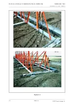
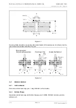
Check antenna spacing after assembly. Repeat for the rear bars and
maintain correct spac-
ing distance between the front and rear bars.Tighten all clamping angles.
2.3
Cable duct assembly
See Vol. 2 Section 2 Chapter 6.
The cable duct sections are numbered and should be assembled according to the drawing.
Sections are joined together by means of blind rivets. When the assembly is complete drill
holes through to the concrete and fix the duct by means of plastic plugs and screws.The lids
should not be put on until cables are installed.
2.4
Antenna assembly
See Vol. 2 Section 2 Chapter 6.
Lay out all masts and stay on the frame work.
Place the bottom ends on al.bar and let all top ends point towards the runway. Notice that the
rear masts have a slot near the bottom end.
Before erecting, all monitor and antenna cables must be installed. Check that the cable mark-
ings are close to the connector. Roll off about one meter from the outer end and form it to a
straight line. Push the cable through the slot in the mast all the way to the top at the same time
as you roll off more of the cable. Gently turn the roll left/right to avoid the obstacles inside the
mast. Leave the rest of the roll in the cable duct.
After all cables are installed the masts can be erected. Secure masts with stays immediately
after erection. Depending on antenna mast height there will be one or two long stays between
front and rear rows.
Tighten all bolts at the mast bottom. Level the masts sideways and tighten the short stays.
Leave the long stays loose, to make it easier to install antennas.
Install the networks. Check the drawing for antenna system in question. Don’t forget the thick
alu.-washer behind the backplate ( pos 9 dwg 16361 A3 )
Install the antennas. The flange at the front can be tightened with all four bolts. Cables should
not be connected at this stage, just secure the rear flange with one bolt.
2.5
Anntenna cables
During this operation the connectors must be protected.
Carefully roll out the cables forward, through the antenna system and towards the runway. All
cables to the left of the centre should be brought to the left of respectively mast and of course
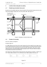
opposite for the other side (see figure 2-3 )
Cut appr. 0,5 m pieces of the flexible conduit, one for each antenna. Push them over the
cables and into the mast, leaving just a few cm outside. Also slide the plastic bushing all the
way to the mast. Pull the cables back and feed them through the hole in the cable duct. Lay
the cables in a loop inside the duct, and connect them to respectively network. Be observant
by pulling so the cables don’t hook on to any obstacles on the ground.
Summary of Contents for NM 7000 Series
Page 7: ...1250 5 167580 17 1 1 6 67 0 167 7 21 200 66 21 1 1 22 1DYLD YLDWLRQ 6 ...
Page 11: ...1250 5 167580 17 1 1 6 67 0 167 7 21 200 66 21 1 1 22 1DYLD YLDWLRQ 6 Figure 2 3 ...
Page 13: ...1250 5 167580 17 1 1 6 67 0 167 7 21 200 66 21 1 1 22 1DYLD YLDWLRQ 6 ...
Page 19: ...1250 5 167580 17 1 1 6 67 0 167 7 21 200 66 21 1 1 22 1DYLD YLDWLRQ 6 ...
Page 21: ...1250 5 167580 17 1 1 6 67 0 167 7 21 200 66 21 1 1 22 1DYLD YLDWLRQ 6 ...
Page 23: ...1250 5 167580 17 1 1 6 67 0 167 7 21 200 66 21 1 1 22 1DYLD YLDWLRQ 6 ...
Page 25: ...1250 5 167580 17 1 1 6 67 0 167 7 21 200 66 21 1 1 22 1DYLD YLDWLRQ 6 ...
Page 27: ...1250 5 167580 17 1 1 6 67 0 167 7 21 200 66 21 1 1 22 1DYLD YLDWLRQ 6 ...
Page 31: ...1250 5 167580 17 1 1 6 67 0 167 7 21 200 66 21 1 1 22 1DYLD YLDWLRQ 6 ...
Page 45: ...1250 5 167580 17 1 1 6 67 0 167 7 21 200 66 21 1 1 22 1DYLD YLDWLRQ 6 ...
Page 55: ...1250 5 167580 17 1 1 6 67 0 167 7 21 200 66 21 1 1 22 1DYLD YLDWLRQ 6 ...
Page 65: ... ...
Page 81: ... ...
Page 111: ... ...
Page 129: ... ...
Page 132: ... ...
Page 134: ...1250 5 167580 17 1 1 6 67 0 167 7 21 200 66 21 1 1 22 1DYLD YLDWLRQ 6 ...
Page 150: ...1250 5 167580 17 1 1 6 67 0 167 7 21 200 66 21 1 1 22 1DYLD YLDWLRQ 6 ...
Page 158: ...1250 5 167580 17 1 1 6 67 0 167 7 21 200 66 21 1 1 22 1DYLD YLDWLRQ 6 ...

