14
ASSA18V
EN
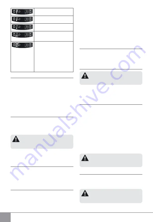
Battery capacity: 60 - 100%
Battery capacity: 30 - 60%
Battery capacity: < 30%
Blinking light
Battery capacity: < 20%. The battery
must be recharged.
Blinking light
Problems with battery.
The display is
activated upon pressing the trigger of
the switch. It may show one of the fol-
lowing battery states:
▪
Low battery ►
Battery has to be
recharged;
▪
Temperature protection has been
actuated ► Battery must be cooled
down prior to resuming operation;
▪
Damaged or unrecognized battery
► Battery has to be replaced
LED WORK AREA LIGHT
The machine is equipped with LED light (3) to illuminate
the work area and improve visibility when drilling in areas
with insufficient light. To turn the LED light on press the
trigger of switch (5). LED light will automatically turn off 5
seconds after releasing the trigger of switch (5).
Electronic control may turn off the excessively overload
-
ed machine in order to protect it. This mode is signalled
by blinking LED work area light (3). The power tool can
be used for its intended purpose after switching it on
again.
REVERSING
(FIG. 3)
The extreme position of lever (4) to the right (viewed from
the rear) is equivalent to anti-clockwise rotation, the ex
-
treme position to the left - to clockwise rotation. When
the ON/OFF switch (5) is depressed lever (4) can not be
actuated.
WARNING:
Reversing can be performed
only when the spindle is not rotating!
Drilling and tightening screws are performed with lever
in extreme position to the left. Removal of screws is per-
formed with lever in extreme position to the right.
SWITCHING ON - SWITCHING OFF
Switching on:
press ON/OFF switch (5).
Switching off:
release ON/OFF switch (5).
The power tool is equipped with a brake. The spindle
stops rotating immediately after releasing the switch le-
ver.
MAX. TIGHTENING TORQUE PRE-SELECTION
Speed and tightening torque are directly correlated. The
lower the speed, the lower is the tightening torque.
The tightening torque can be adjusted in two ways:
- By pre-selecting the speed and max. tightening torque;
- By smooth adjusting the speed / tightening torque.
Pre-selecting the speed and max. tightening torque can
be accomplished by pressing button (7). Upon pressing
button (7) once, indicator (6) shows the selected setting.
Repeatedly pressing the button (7) will change the three
settings for maximum torque and this will be indicated by
one, two or three LEDs on indicator (6). One LED corre
-
sponds to the lowest speed / torque, and three LEDs - to
the highest speed / torque.
The selected range is being saved even if the machine
has been switched off or the battery has been removed.
SMOOTH ELECTRONIC SPEED / TORQUE
CONTROL
Light pressure on ON/OFF trigger switch (5) results in
low rotation speed, further pressing the switch results in
smooth increase of the rpm to maximum upon reaching
the extreme position.
INSERTING AND REMOVING BITS
WARNING:
Remove the battery or set the
forward/reverse switch (4) in central (neutral) position.
Inserting the bit:
Align the square opening of the socket
bit to the tool holder (2) and press it firmly.
Removing the bit:
Pull the socket out to remove it.
OPERATING THE TOOL
Impact operation starts automatically when the load ex-
ceeds certain level. Pushing the trigger switch at no load
will result only in change of speed.
The fastening torque depends on the duration of impact
operation. Generally, maximum torque is achieved after
5 seconds of impact operation. Further operation will
result only in slight torque increase. Prolonged impact
operation may cause motor damage or burning.
The torque depends on the length, grade and diameter
of the screw. It depends also on the strength of material
to be fastened (wood, metal, etc.) and the type of washer
used. Operate the tool after calculating the appropriate
impact operation time by performing a trial fastening
and measuring the actually achieved torque by a torque
wrench.
WARNING:
Power tool with a faulty switch is
dangerous and shall be repaired before use.
SCREWING / UNSCREWING
Install a bit that matches the screw, align the bit into the
grooves of the screw head, and then tighten it.
Push the impact driver just enough to keep the bit in con-
tact with the screw head.
WARNING:
Overtightening may result in
breaking the screw or damaging the bit!
Applying the impact driver for too long may tighten the
Summary of Contents for ASSA18V
Page 2: ...2 1 3 4 C 3 5 2 4 12 6 7 8 9 10 10 A B 11 9 100 60 30 20 0 20 ...
Page 58: ...ASSA18V ...
Page 59: ...Pos Id Benennung des Erzatzteils Description ...
Page 60: ......
Page 61: ......
Page 62: ...1806R01 ...


