CONFIDENTIAL AND PROPRIETARY
©Norsat International Incorporated (“Norsat”) All Rights Reserved
2021-02-16 INS001201 Rev B
9
2. Interface Control
2.1 INTRODUCTION
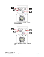
The unit has three connectors on the input side of the housing and one waveguide port on the output side.
The interface for these connectors is detailed in this document.
On the input side, there are the following connectors:
•
J1
–
IF or RF Input; N-Type Jack for BUC; K-Type Jack for SSPA
•
J2
–
Ten-pin circular connector for M&C
•
J3
–
Four-pin circular DC power connector
•
J6
–
Ground terminal
Figure 2-1 Input Connections for ATOM Ka 25W/40W
BUC Unit (N-Type Jack Shown)
J3
Figure 2-2 Input Connections for ATOM Ka 25W/40W
SSPA Unit
J1
J2
J6
J6
J2
=
J3
J1

