background image


ATOM 100-250W BUC & SSPA 

Revision 2.2 

908236 


10 

908236_r2.2 - Operator Manual ATOM KU 

100-250W.doc 


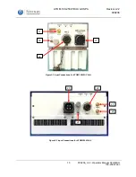
J1 

J6 

J2 

J3 

Figure 2-2 Input Connections for ATOM 100W AC Unit


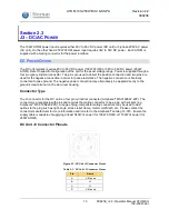
J1 

J2 

J3 

J5 

J6 

Figure 2-3 Input Connections for ATOM 250W Unit


Summary of Contents for ATOM 100W BUC

Page 1: ...sion 2 2 908236 1 908236_r2 2 Operator Manual ATOM KU 100 250W doc ATOM 100 250W BUC SSPA Operator s Manual Document Number 908236 Revision 2 2 Norsat International Inc 110 4020 Viking Way Richmond British Columbia Canada V6V 2L4 ...

Page 2: ... to improve reliability function or design Norsat does not assume any liability arising out of the application or use of any product or circuit described herein Norsat does not convey any license under its patent rights or the rights of others TECHNICAL SUPPORT This manual provides engineers with information necessary to operate the applicable system Technical support is available from Norsat Nors...

Page 3: ...or RF Output and Ground Connection JG FL 14 04 29 1 2 5964 Update Address JL FL 14 09 05 2 0 6518 Update for Ethernet Interface Update M C Protocol SM JG CW 15 12 15 2 1 7127 Update IP Address Restore Info JG 16 01 26 2 2 7204 Update M C Interface Options Update to include 250W JG AY JG 16 02 16 Non Digital Approval Only if required Scan this page with signature and attach to Change Order if this ...

Page 4: ...F Input 12 J5 Trigger Input for Mute Unmute Optional for ATOM 100W 12 J6 Ground Terminal 12 SECTION 2 3 J3 DC AC POWER 13 DC Power Option 13 3 Phase AC Power Option 14 SECTION 2 4 J2 MONITOR AND CONTROL INTERFACE 15 Monitor and Control Interface Pinout 15 Serial Port Interface RS 485 RS 232 19 Ethernet Interface ATOMWeb 25 SECTION 2 5 J4 RF OUTPUT 27 SECTION 2 6 GROUND CONNECTION 27 SECTION 2 7 IN...

Page 5: ... RJ 45 Plug Pinout 18 Figure A 3 1 100W SSPA with AC Input SMA Output 32 Figure A 3 2 100W BUC SSPA with DC Input WR62 75 Output Fan Cooled 33 Figure A 3 3 100W BUC SSPA with DC Input WR62 75 Output Baseplate Cooled 34 Figure A 3 4 250W BUC SSPA with DC Input WR62 75 Output Baseplate Cooled 35 LIST OF TABLES Table 1 1 Input and Outputs 7 Table 2 1 DC Unit J3 Connector Pinout 13 Table 2 2 AC Unit J...

Page 6: ...ers ATOMSKUxxx 100 250W ATOMBKUxxx 100 250W This includes any ATOM that uses the 100 250W P1dB Ku Extended Band 13 75 14 5GHz mechanics such as a custom frequency band or power derated output unit SSPA SOLID STATE POWER AMPLIFIER If this unit is a SSPA the RF input signal is amplified to the specified power BUC BLOCK UP CONVERTER AND AMPLIFIER If this unit is a BUC the IF input signal is upconvert...

Page 7: ...d Waveguide WR62 optional frequency dependent ELECTRICAL INTERFACE M C Connector a ten pin connector is used to interface with a host computer See Section 2 4 J2 Monitor and Control Interface for detailed description of the pinouts Power Connector DC Units use a four pin connector and AC units use a six pin connector to provide power to the ATOM See Section 2 3 J3 DC AC Power for detailed descript...

Page 8: ...F load 100W min or connected to the feed of a terminal Do not obstruct the RF output or feed output with any body part W A R N I N G Do not allow equipment to be standing in water While the BUC SSPA is designed to be used outdoors the equipment is not designed to operate in standing water Failure to follow this precaution could result in electric shock and injury to persons C A U T I O N Do not al...

Page 9: ...on the output side The interface for these connectors is detailed in this document On the input side there are the following connectors J1 IF or RF Input N Type Jack or SMA Type Jack J2 Ten pin circular connector for M C J3 Four pin circular power connector for DC unit or six pin circular power connector for AC unit J5 optional and not shown for ATOM 100W units Female SMA mute unmute trigger input...

Page 10: ...250W BUC SSPA Revision 2 2 908236 10 908236_r2 2 Operator Manual ATOM KU 100 250W doc J1 J6 J2 J3 Figure 2 2 Input Connections for ATOM 100W AC Unit J1 J2 J3 J5 J6 Figure 2 3 Input Connections for ATOM 250W Unit ...

Page 11: ...250W doc On the output side there is one connector J4 WR75 or WR62 waveguide RF output Optional Waveguide to Coax adaptor J4 Figure 2 6 Standard Waveguide Output for ATOM 250W units J4 Figure 2 5 Optional Waveguide to Coax adaptor Figure 2 4 Standard Waveguide Output for ATOM 100W units ...

Page 12: ...m load at DC Do not exceed 7 VDC on this port An external DC block is required if the modem or signal source supplies a DC voltage J5 TRIGGER INPUT FOR MUTE UNMUTE OPTIONAL FOR ATOM 100W The TRIG input is a 50 ohm type SMA connector This is an optional feature to be specified at time of order The input must be at TTL compatible voltage levels 0 5V 0 25V J6 GROUND TERMINAL A 10 32 screw and lock wa...

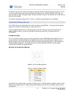
Page 13: ...ance The negative connection is internally connected to case ground The negative power connection may alternatively be applied directly to the ground screw terminal on the aluminum housing Connector Type The J3 connector for the DC unit is a four pin cylindrical connector Amphenol MS3102E22 22P The connector is a receptacle with pins and requires the mating connector to be a plug with sockets e g ...

Page 14: ...iver the 3 phases of the AC power one pin is connected to the case ground of the unit and two pins are unconnected Connector Type The J3 connector for the AC unit is a six pin cylindrical connector AMPHENOL DL3102A18 12P The connector has a Pre Earth First Make Last Break feature where the ground terminal mates first and provides a path for any stray voltage to be shunted to a safe ground avoiding...

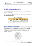
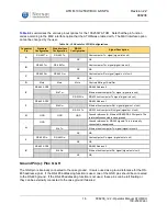
Page 15: ...available with each option Table 2 3 M C Interface Options Orderable Option Communication Interfaces RS 485 Addressable RS 485 RS 232 Web Interface Standard X X RS 232 Option X Web Interface Option X X MONITOR AND CONTROL INTERFACE PINOUT The M C interface is a ten pin miniature circular connector This connector is a MIL C 26482 Series 1 receptacle shell size 12 10 pin Amphenol part number 71 5701...

Page 16: ...32 Rx RS 232 host computer Tx signal signal into unit F RS 485 ADD1 RS 485 Address 1 Eth Rx Ethernet host computer Rx signal signal out of unit RS 232 Tx RS 232 host computer Rx signal signal out of unit G GND GND GND Ground reference for Ethernet RS 485 RS 232 signals This is internally connected to case ground H GND Ground reference for RS 485 signals This is internally connected to case ground ...

Page 17: ...mute Pull Down 0V Muted 5V Unmuted Floating Muted Sample 3 5V Unmute Pull Up 0V Muted 5V Unmuted Floating Unmuted Note that the ATOM mute state can also be controlled through the M C interface The software mute setting takes priority over the hardware pin Refer to Command Details section for details RS 485 Port Pins A B C J G These five pins form a standard four wire RS 485 serial port with Rx Rx ...

Page 18: ... 1 0 1 0 2 0 1 1 3 1 0 0 4 1 0 1 5 1 1 0 6 1 1 1 7 Ethernet Interface Option Pins E F H K These four pins form a standard 10 100Mbps Ethernet link Table 2 7 and Figure 2 10 summarize how to construct an Ethernet M C cable to access the web interface Table 2 7 Ethernet Cable Pinout ATOM Connector Twisted Pair Cable RJ 45 Connector Description E Wht Grn 1 Ethernet host computer Tx signal signal into...

Page 19: ... screen for ease of entry The CLI does not provide a prompt instead commands can be entered at a blank line The CLI requires that all sent commands be terminated with either a carriage return character denoted CR in the following sections if the device is operating in Non addressed Mode or with both a carriage return character and a line feed character denoted CR LF if the device is operating in A...

Page 20: ...5 address will be ignored Non addressed commands will also be ignored by devices with an RS 485 address between 0 and 6 inclusive Addressed Commands and their corresponding responses also include a CRC character immediately before the terminating CR and LF This unsigned 8 bit CRC character can be any value between 0 and 255 inclusive and is calculated using the portion of the command string or res...

Page 21: ...s was not valid Missing Parameter A required parameter was not provided Inconsistent Values The values provided to at least one parameter is not consistent with the values provided to other parameters Bus Error The hardware required to process the command does not exist on this device e g BUC specific command sent to an SSPA Due to the inherent collisions that can occur between multiple addressed ...

Page 22: ... of the following values AMP Ku100 BUC Ku100 AMP Ku250 BUC Ku250 Part Names that start with AMP denote SSPAs while Part Names that start with BUC denote BUCs Software Version string The software version number in the format Major Minor Revision_Build Serial Number string A concatenation of the Part Name a hyphen and the actual numeric Serial Number of the device RS485 Address UINT16 The address us...

Page 23: ...ith 0 1 dBm accuracy Device Temperature INT16 The temperature of Power Module 8 in degrees Celsius Values range from 40 to 125 Example Tx getstatus CR Rx CR LF ok fault 0x0 fwdpwr 10 4 revpwr 21 3 temp 42 CR LF Notes Power Faults indicate that one of the voltages monitored by the device s internal voltage monitor has dropped too low PLL Faults typically indicate that no 10 MHz reference signal is ...

Page 24: ...be safely ignored resetfaults This command resets the Over Temperature Fault for the ATOM device if the current System Temperature is below the device s fault reset temperature Command Format resetfaults CR Response Format CR LF ok CR LF Example Tx resetfaults CR Rx CR LF ok CR LF Notes The default fault threshold temperature is 90 C The default fault reset temperature is 70 C getmute This command...

Page 25: ...dless of the device s fault state or the state of the hardware mute pin If Mute Command is set to 0 then the device s mute state will be controlled by the device s fault state and the state of the hardware mute pin ETHERNET INTERFACE ATOMWEB On units equipped with the Ethernet option an integrated HTTP Web Server allows the user to access a web based version of the ATOMControl software to control ...

Page 26: ...er INS001085 Changing the ATOM s IP Address The factory default IP address of the BUC is 192 168 77 30 but it can be user configured through the Network and Port Configuration webpage To change the ATOM s IP Address connect the ATOM as described above launch a web browser and then navigate to the following address http 192 168 77 30 index_cong html Specify the desired IP Address in the text boxes ...

Page 27: ...rnet web server should be the only device listed in the summary 10 Follow the instructions in the preceding section to restore the IP Address to the desired setting Section 2 5 J4 RF OUTPUT The RF output port is either WR75 standard or WR62 optional frequency dependent square waveguide flange The unit is supplied with two screw lengths four 6 32x3 8 and four 6 32x7 16 it is the user s responsibili...

Page 28: ...lts TEMP Red On Over temperature fault Off No over temperature fault When power is first applied an LED test will be performed and all LEDs will illuminate for 1 second The POWER LED will illuminate whenever power is applied to the unit The FAULT LED will illuminate when an internal regulator is not producing the proper voltage the internal temperature is too high or the PLL has lost phase lock Th...

Page 29: ...se in an outdoor environment and is sealed to prevent water ingress Ensure the waveguide and or feed connected to J4 are also sealed with gaskets to prevent water ingress Section 3 2 FANS BASEPLATE COOLING The standard ATOM configuration employs an integrated radiator and IP55 fans to cool the unit A minimum clearance of 1 inch must be maintained around the air intake and exhaust during use The fa...

Page 30: ...rizes general specifications applicable to most 100 250W ATOM units Please refer to the specific ATOM datasheet available on the Norsat website for complete unit specifications Table 3 1 General 100 250W ATOM Specifications Parameter Specifications RF Power Output P1dB 100W 250W Gain min 60dB 65dB Operating Temperature with fans 40 C to 60 C Storage Temperature 54 C to 80 C Thermal Shutdown Temper...

Page 31: ...or a period of one 1 year from the ship date unless otherwise stated in the Offer Terms and Conditions The warranty does not cover units that have been damaged through improper use or physical damage e g dropped units been modified altered or repaired by the user the security label s removed or damaged the serial number label removed or altered To obtain warranty repair service please contact Nors...

Page 32: ...00 2 665 3 511 4 830 0 0 0 0 1 031 2 131 2 306 2 181 3X 3 331 6 431 1 060 2 830 3 900 4 930 5 330 0 500 2 665 4 830 0 0 0 899 3X 0 225 3X 10 475 10 700 11 689 2X 1 031 2X 1 831 2X 2 631 0 0 2X 0 365 2X 2 665 2X 4 965 3X 0 225 3X 10 475 INTAKE 6X 8 32 0 25 BOTH SIDES EXHAUST INTAKE 3X 8 32 0 38 BOTH SIDES 6X 1 4 20 0 50 Figure A 3 1 100W SSPA with AC Input SMA Output ...

Page 33: ... 2X 2 631 0 0 0 0 0 500 2 665 4 830 1 181 2 131 2 306 1 060 2 830 4 100 4 930 5 330 2 181 3X 3 331 0 0 2 081 3X 3 331 0 500 2 665 3 511 4 830 0 0 2X 0 365 2X 2 665 2X 4 965 3X 0 225 3X 10 475 INTAKE 6X 8 32 0 25 BOTH SIDES EXHAUST INTAKE 3X 8 32 0 38 BOTH SIDES 6X 1 4 20 0 50 Figure A 3 2 100W BUC SSPA with DC Input WR62 75 Output Fan Cooled ...

Page 34: ...0 0 0 0 0 0 500 2 665 4 830 2 181 3X 3 331 1 031 3 581 1 060 2 830 3 900 0 0 4X 0 680 3X 2 740 5X 4 830 3X 8 050 4X 10 020 2X 0 750 5X 2 540 5X 3 685 3X 5 350 0 3 581 0 915 0 225 10 475 10 700 1 031 1 831 2 631 0 3X 8 32 0 38 BOTH SIDES 17X 8 32 0 25 BOTH SIDES 6X 8 32 0 25 BOTH SIDES Figure A 3 3 100W BUC SSPA with DC Input WR62 75 Output Baseplate Cooled ...

Page 35: ... 10 990 0 2 481 0 0 581 2X 0 400 6 547 2X 0 831 2X 3 231 0 0 1 231 2X 2 831 6 271 2X 0 350 11 688 12 000 12 891 0 087 11 390 12 891 0 500 2X 1 4 20 UNC 10 32 UNF 0 220 WR75 FLANGE SHOWN 1 4 20 UNC 0 500 INTAKE EXHAUST WAVEGUIDE OUTPUT FLANGE INTAKE 1 4 20 UNC 0 500 Figure A 3 4 250W BUC SSPA with DC Input WR62 75 Output Baseplate Cooled ...

Page 36: ...ronym Definition BUC Block Upconverter AMP Amplifier C Celsius CR Carriage Return character ASCII dBm Decibel milliwatts DC Direct Current ESD Electrostatic Discharge freq Frequency GHz Gigahertz GND Ground IF Intermediate Frequency kHz kilohertz LF Line Feed character ASCII M C Monitor and Control MHz Megahertz mm Millimeter N A Not Applicable ppm Pulses per minute RF Radio Frequency RX Receive S...

Reviews: