background image

© Norsat International Inc. 

(“Norsat”) All Rights Reserved  

2021-12-20 DOC-001527 Rev A


31 

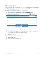
3.9  Factory Reset 

Performing a factory reset on the ODU will reset all user configurable values including Network 
Settings, Current Limits, ULC settings, LNB bands, and SNMP settings.  

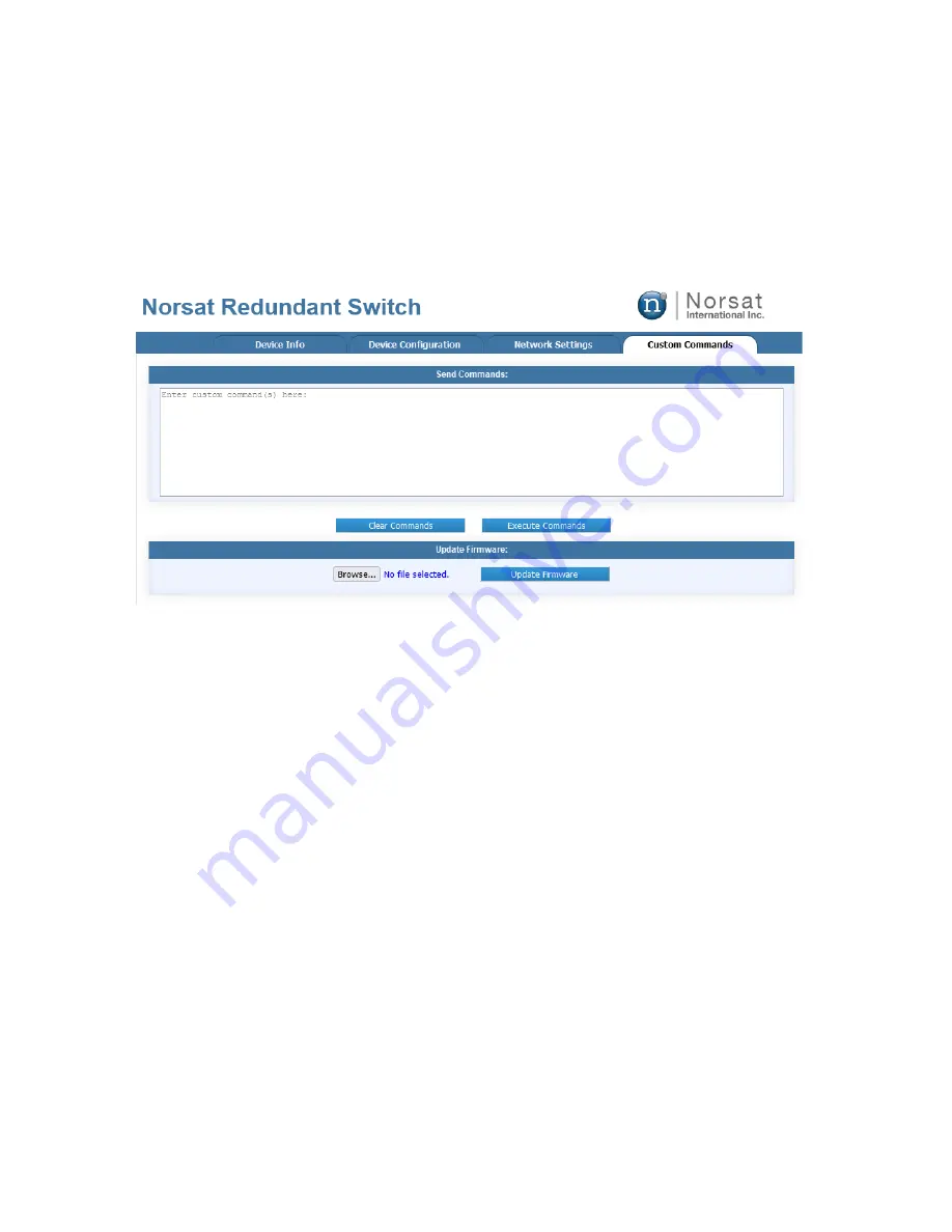
3.9.1  Web Interface Factory Reset 

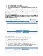
To perform a factory reset of the ODU through the web interface: 

1.  Open the web interface and navigate to the 

Custom Commands

 Page 


2.  In the 

Send Commands

 section, type 

factoryreset

”. 

3.  Click 

“Execute Commands”. 

4.  A window pops up asking you to confirm. 

Click OK.


5.  Factory reset is complete. If you have updated the network settings, they will return to 

default and the web interface will need to be refreshed.  
 

3.9.2  SNMP Factory Reset 

To perform a factory reset of the ODU over SNMP: 

1.  Open an SNMP client. 
2.  Write 1 to the factoryReset parameter. 


Summary of Contents for LNB

Page 1: ...USER MANUAL LNB 1 1 Redundant Switch ODU FW Version 1 0 0 IDU FW Version 1 0 0 ...

Page 2: ...U Setup 6 2 3 ODU IFL installation 16 2 4 IDU installation Optional 17 2 5 Safety Ground 18 ODU Monitoring and Control 19 3 1 Fault Monitoring 19 3 2 Operation Mode 19 3 3 LNB Power 20 3 4 Default Network Settings 21 3 5 LNB Replacement 21 3 6 Web Interface 21 3 7 SNMP 27 3 8 ODU Manual Override Switch 30 3 9 Factory Reset 31 IDU Operation 34 4 1 Front Panel 34 4 2 LCD Screen 36 4 3 IDU Web Interf...

Page 3: ...erved 2021 12 20 DOC 001527 Rev A 3 Acronyms AC Alternating Current CI Control Interface IDU Indoor Unit IFL Interfacility Link LNB Low noise Block Downconverter RF Radio Frequency SNMP Simple Network Management Protocol ULC Universal LNB Controller ...

Page 4: ...quipment notexpressly approvedby the manufacturer could void the user s authority to operate the equipment Warning Accessories and Devices Use of non approved accessories or devices may lead to a degradation in performance damage to equipment or potential hazards Warning AC Power This device uses AC power Proper grounding of equipment is necessary for safety purposes ...

Page 5: ...alls outside of a specified window the RSW automatically switches to the backup LNB 1 2 System 1 2 1 Headless Operation ODU Only The RSW is headless meaning that it can be operated without the use of an Indoor Unit IDU All monitoring and control M C can be performed over Ethernet using the Web Interface or via SNMP The Outdoor Unit ODU contains all control circuitry and is connected to the user s ...

Page 6: ...em is powered on Inspect all cables for damage prior to connecting them to the system 2 2 ODU Setup 2 2 1 Ku Ka Band LNB Installation LNB installation for Ku band and Ka band components are identical except different sized fasteners are provided The following components are included with the LNB mounting kit Item 1 Socket Cap Screw Item 2 Washer Item 3 Loctite 8x for 1 1 RSW 12x for 2 1 RSW 8x for...

Page 7: ...In 2 IF Out 3 and LNB 3 are only present in 2 1 redundant switches Repeat the following steps for each LNB interface 1 Remove any tape on the waveguide interface 2 Insert the gasket included with the LNB into the groove on the LNB LNB 1 LNB 2 LNB 3 Rx In 1 Rx In 2 IF Out 1 IF Out 2 IF Out 3 LNB Gasket ...

Page 8: ...ree drops of Item 3 Repeat this step for four times 4 Install the LNB onto the Rx In of redundant switch using the Item 1from step 3 above and one Item 2 on each Item 1 with Tool 1 5 Connect the LNB to the IF Out port with the matching number for the LNB position i e LNB 1 connects to IF OUT 1 Item 1 Item 3 LNB Item 1 Item 2 ...

Page 9: ...are included with the LNB mounting kit Item 1 Socket Cap Screw Item 2 Washer Item 3 Threadlocker 14x 14x 1x Item 4 Gasket Item 5 Adaptor Plate Item 6 Set Screw 2x 2x 6x Item 7 Nut 6x The following tools are required not included with the mounting kit Tool 1 Hex Key Tool 2 Hex Key Tool 3 Wrench 3 16 1 8 7 16 Note the interfaces shown below ...

Page 10: ... Norsat International Inc Norsat All Rights Reserved 2021 12 20 DOC 001527 Rev A 10 LNB 1 LNB 2 Rx In IF Out 1 IF Out 2 ...

Page 11: ...ing steps for each LNB interface 1 Remove any tape on the waveguide interface 2 On the end opposite to the socket head of Item 6 apply two to three drops of Item 3 Complete this step for three Item 6 3 Fasten Item 6 from step 2 above into the LNB interface using Tool 2 Item 6 Item 3 Socket Head Item 6 ...

Page 12: ...rved 2021 12 20 DOC 001527 Rev A 12 4 Insert Item 4 into the LNB interface on the redundant switch and align Item 5 onto Item 6 installed from step 3 above 5 Insert the gasket included with the LNB into the groove on the LNB Item 4 Item 5 LNB Gasket ...

Page 13: ...OC 001527 Rev A 13 6 On the thread of Item 1 apply two to three drops of Item 3 Complete this step for five Item 1 6 Install the LNB onto the Rx In of redundant switch using Item 1 fromstep 5 above and one Item 2 on each Item 1 with Tool 1 Item 1 Item 3 Item 2 Item 1 ...

Page 14: ... 7 Fasten Item 7 onto Item 6 installed onto the redundant switch using Tool 3 8 Tighten all surrounding screws and nuts to fasten the LNB onto the redundant switch 9 Connect the LNB to the IF Out port with the matching number for the LNB position i e LNB 1 connects to IF OUT 1 Item 7 ...

Page 15: ...ion Refer to the diagram below for the location of all mounting holes on the redundant switch baseplate Depending on the redundant switch configuration some holes may be inaccessible Follow these general guidelines when mounting the redundant switch Engage a minimum of 15 holes Use medium strength threadlocker ...

Page 16: ...ernet cable 1 x RF Cable 1 Locate the ODU side of the IFL labeled ODU 2 Attach the RF cable to the IF1 connector as shown below 3 Attach the PWR connector to the ODU Ensure that the cable is threaded onto the connector 4 If you have purchased the optional IDU proceed to Section 2 4 If the RSW is being operated in the headless configuration you can now power on the system by connecting the PWR cabl...

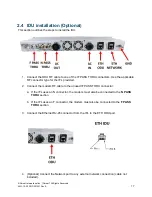
Page 17: ...F connector type for the IFL provided 2 Connect the modem RF cable to the unused IF PASS THRU connector a If the IFL uses an N connector the modem must also be connected to the N PASS THRU section b If the IFL uses an F connector the modem must also be connected to the F PASS THRU section 3 Connect the Ethernet RJ 45 connector from the IFL to the ETH ODU port 4 Optional Connect the Network port to...

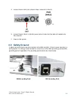
Page 18: ...le Ensure that the cable is threaded onto the connector 7 Power on the system 2 5 Safety Ground A safety ground connection point is provided on the ODU and IDU If the AC power input has no earth ground it is strongly recommended to connect one at the ODU grounding point and IDU grounding point if applicable The grounding point locations are shown below ODU Grounding Point IDU Grounding Point ...

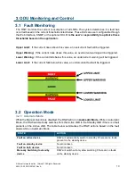
Page 19: ...f the current falls below this value an undercurrent warning will be triggered Lower Limit If the current falls below this value an undercurrent fault will be triggered 3 2 Operation Mode 3 2 1 Automatic Mode While the Manual Override is disabled the RSW will run in Automatic Mode While in Automatic Mode the RSW automatically switches from the Active LNB to the Standby LNB if there is a fault pres...

Page 20: ...taken Switching to standby device RSW will switch to the standby device 3 3 LNB Power 3 3 1 Integrated ULC The RSW has an integrated Universal LNB Controller ULC which can be configured by the user When the ULC setting is enabled both the Active and Standby LNB receive power from the ULC The table below outlines the output voltage and tone for each configurable band In the case that a single band ...

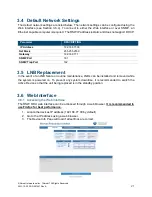
Page 21: ...Gateway 192 168 77 1 SNMP Port 161 SNMP Trap Port 162 3 5 LNB Replacement In the event of an LNB failure or routine maintenance LNBs can be installed and removed while the system is powered on To prevent any system downtime it is recommended to switch the Active Device so that the unit being replaced is in the standby position 3 6 Web Interface 3 6 1 Accessing the Web Interface The RSW ODU web int...

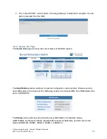
Page 22: ...ll show the current status of the RSW system The Identification section will show the device configuration serial number firmware version and LNB model In the case that the LNB being used is not a Norsat LNB the LNB Model will be set to UNKNOWN The Status section will show the Active Device LNB1 LNB2 the Standby Device LNB1 LNB2 the Operation Mode Automatic Manual Override Mode and the current ULC...

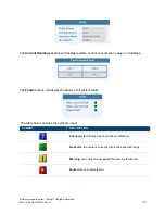
Page 23: ...nsumption values in milliamps The Faults section will display the status of all system faults The table below outlines the symbols used SYMBOL DESCRIPTION Unknown fault status has not yet been initialized No Faults the value is currently within the expected range Warning the value has exceeded the warning threshold Fault there is a fault present ...

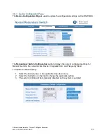
Page 24: ... ODU The Redundancy Switch Configuration section displays the current configured settings for Manual Override the current Active Device Integrated ULC and Frequency Band To Update the RSW settings 1 Select the desired value in the applicable drop down menu 2 Select the Set button on the right to change the applicable setting 3 The system controls will be temporarily disabled as the system is updat...

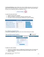
Page 25: ...dvanced Settings 1 Update the setting value of interest 2 Select the Set button on the right to change the applicable setting 3 The system controls will be temporarily disabled as the system is updated 3 6 4 Network Configuration Page The Network Configuration page shows the current network settings of the ODU To update the network settings 1 Change the IP address Subnet and Gateway to the desired...

Page 26: ...nds Page The Custom Commands page allows the user to send command strings to the RSW Note This interface should not be used during normal operation This also allows the user to update the RSW firmware see Section 3 6 6 3 6 6 Firmware Update To perform a firmware update on the RSW ODU perform the following steps 1 Obtain a valid RSW ODU firmware update file from Norsat 2 Open the Web Interface in F...

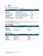
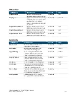
Page 27: ...ersion of SNMP running on the RSW V1 V2 Read Community String Read Community String Public Write Community String Write Community String Public 3 7 2 SNMP parameters To access the RSW SNMP parameters download the latest MIB file from Norsat A summary of all accessible parameters is shown below Product Configuration PARAMETER DESCRIPTION ACCESS Range Product Configuration Norsat RSW Product Configu...

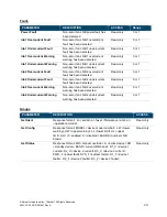
Page 28: ...evice Config PARAMETER DESCRIPTION ACCESS Range Max Current Maximum LNB current before an overcurrent fault is triggered Read write 0 to 500 Min Current Minimum LNB current before an undercurrent fault is triggered Read write 0 to 500 Upper Warning Upper warning threshold for LNB current If LNB current is above this value a warning will be triggered Read write 0 to 500 Lower Warning Lower warning ...

Page 29: ...y 0 or 1 lnb2 Undercurrent Fault Non zero if an LNB 2 undercurrent fault has been detected Read only 0 or 1 lnb2 Overcurrent Warning Non zero if an LNB 2 overcurrent warning has been detected Read only 0 or 1 lnb2 Undercurrent Warning Non zero if an LNB 2 undercurrent warning has been detected Read only 0 or 1 Groups PARAMETER DESCRIPTION ACCESS Get Ident Response format sn serial no fwver firmwar...

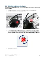
Page 30: ...e used 1 If the device being switched to is in a fault state enable Manual Override Mode 2 Remove the cover on the manual override switch 3 Turn the override switch to the desired position The white lines on the switch indicate the current active path Do not hold the switch in the new position if the system is trying to switch back to the previous device This may cause damage to the motor 4 Replac...

Page 31: ...ory reset of the ODU through the web interface 1 Open the web interface and navigate to the Custom Commands Page 2 In the Send Commands section type factoryreset 3 Click Execute Commands 4 A window pops up asking you to confirm Click OK 5 Factory reset is complete If you have updated the network settings they will return to default and the web interface will need to be refreshed 3 9 2 SNMP Factory...

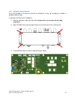
Page 32: ... to the ODU over Ethernet it may be necessary to perform a hardware factory reset To perform a factory reset in hardware 1 Remove the power cable from the ODU Power to the unit must be off for safety purposes 2 Open the ODU lid by unscrewing the four screws on the top of the controller box 3 Locate the DIP switch on the circuit board shown below ...

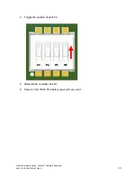
Page 33: ...Norsat International Inc Norsat All Rights Reserved 2021 12 20 DOC 001527 Rev A 33 4 Toggle the position of switch 4 5 Reinstall the controller box lid 6 Power on the RSW The factory reset will now occur ...

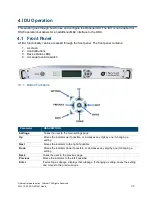
Page 34: ...s 3 Device status LEDs 4 A manual override switch 4 1 1 Button Functions Parameter DESCRIPTION Settings Takes the user to the main settings page Up Moves the indicator up if possible or increases any digit by one if changing a setting Next Moves the indicator to the right if possible Down Moves the indicator down if possible or decreases any digit by one if changing a setting Back Takes the user t...

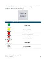
Page 35: ...e status of each device at a quick glance In the 1 1 RSW configuration the DEVICE 3 LED will not be used LED STATUS DESCRIPTION Solid Geen Status is GOOD Yellow Solid Device is in STANDBY Red Solid Device is in a WARNING state Red Flashing Slow Device is in an ALARM state Red Flashing Fast Device ERROR Off Device is NOT PRESENT ...

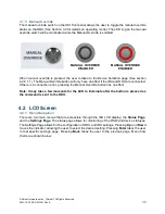
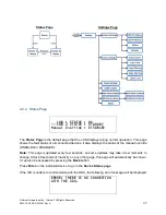
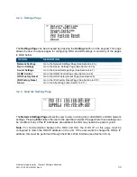
Page 36: ... effect if the IDU and ODU are connected If there is a connection error pressing the Manual Override button has no effect Note It may take a few moments for the LED to illuminate after the button is pressed as the command is sent to the ODU 4 2 LCD Screen 4 2 1 Menu Navigation There are two main menus that are accessible through the IDU LCD display the Status Page and the Settings Page The status ...

Page 37: ...ted devices It also displays the status of the manual override ENABLED or DISABLED Note This page is updated every few seconds so some updates may take a few moments to change After 20 seconds of inactivity on any other page this page will automatically be shown It can also be accessed by pressing the Back button Press Enter on the indicated device to go to the Device Status page If the IDU is una...

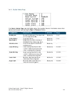
Page 38: ...nd LNBs Read write 1 to 4 Current Band Current ULC band Read only 1 to 4 Band Switch ENABLED if the LNB is multi band DISABLED if the LNB is single band Read only Actual Current Current consumption in mA for the selected device Read only Lower Warning Lower warning threshold for LNB current If LNB current is below this value a warning will be triggered Read write 0 to 500 Upper Warning Upper warni...

Page 39: ...l Page See Section 4 2 8 ODU Factory Reset Go to the ODU Factory Reset Page See Section 0 IDU Factory Reset Go to the IDU Factory Reset Page See Section 4 2 10 About Go to the About Page See Section 4 2 11 4 2 5 Network Settings Page ODU IP 192 168 077 030 IDU IP 192 168 077 031 SUBNET 255 255 255 255 GATEWAY 192 168 077 001 The Network Settings Page allows the user to view or change the current O...

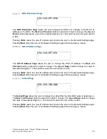
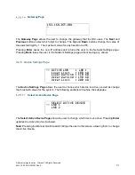
Page 40: ...e user to change the IDU s IP address The Next and Previous buttons select which digit to change The Up and Down buttons change the value of the selected digit by 1 The maximum value for each section is 255 Pressing Enter saves the new IP address and returns the user to the Network Settings page Pressing Back takes the user to the Network Settings page without saving any values Subnet Page 255 255...

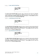
Page 41: ...he user to the Network Settings page without saving any values 4 2 6 Device Settings Page ACTIVE LNB LNB 1 Lower Limit 100 mA Lower Warning 110 mA Upper Warning 190 mA Upper Limit 200 mA The Device Settings Page allows the user to choose which device is active as well as change the threshold values for the system The following sections will outline the subpages Select Active Device Page SELECT ACT...

Page 42: ...LOWER WARNING 110 mA The Lower Warning Threshold Page allows the user to change the lower warning threshold measured in mA Pressing Previous and Next allows the user to select which digit to change Pressing Up and Down changes the value of the digit by 1 Pressing Enter saves the value and returns the user to the Device Settings Page Upper Warning Threshold Page LNB CURRENT UPPER WARNING 190 mA The...

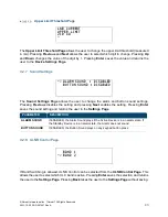
Page 43: ... the alarm and button sound settings Pressing Previous disables the setting and pressing Next enables the setting Pressing Enter saves the sound setting and returns the user to the Settings Page PARAMETER DESCRIPTION ALARM SOUND If ENABLED the Alarm Sound plays if the Active Device is in an alarm state If the Standby Device is in an alarm state the Alarm does not sound BUTTON SOUND If ENABLED the ...

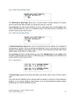
Page 44: ...s the IP addresses in the IDU s memory and the sound settings This is only for the IDU and will not include the IP addresses in the ODU s memory It will also not include the threshold values limits and warnings Active Device or active band Pressing Enter when NO is selected takes the user to the Settings Page Pressing Enter when the YES is selected takes the user to a confirmation page If the fact...

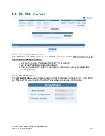
Page 45: ...se Firefox for best performance 1 Locate the devices IP address 192 168 77 31 by default 2 Go to the IP address using a web browser 3 The Log Output at the bottom of the page will display any system messages after loading the page 4 3 2 IDU Identification The IDU Identification section displays the Serial Number Device Configuration 1 1 or 2 1 BUC or LNB and Firmware Version of the IDU These value...

Page 46: ...puts on the right 2 Press the Save Settings button to implement the changes 3 Power cycle the IDU after updating the network settings for the change to take effect The web page will now be accessible through the updated IP address 4 3 4 IDU Configuration The IDU Configuration section displays the sound settings for the IDU with the current values on the left To update the sounds settings 1 Select ...

Page 47: ...the firmware file 4 Click Update Firmware 5 A progress bar will indicate how much of the file has been transferred to the IDU Do not close the Web Interface or power off the RSW while the firmware update is in progress 6 Once the file has been successfully transferred verify that the firmware version has been updated in either the About Page or the Web Interface 4 3 6 Log Output The Log Output sec...

Page 48: ...h the network for the devices MAC address 8 If the IP address has been lost a hardware factory reset may be required see Section 3 9 3 9 If the problem persists contact Norsat customer support System Power Fault is present 1 If the LNBs are being powered by the on board ULC open the ODU Web Interface and confirm that the ULC is enabled 2 If the LNBs are being powered by an external source ensure t...

Page 49: ...l Rights Reserved 2021 12 20 DOC 001527 Rev A 49 System Maintenance NO DESCRIPTION FREQUENCY 1 Inspect all cables for damage Once per month 2 Toggle the active LNB to standby to test that the system is working as expected Once per month ...

Page 50: ...ing applications Norsat s products and services include customizable satellite components portable satellite terminals maritime solutions and satellite networks The company s products and services are used extensively by telecommunications services providers emergency services and homeland security agencies military organizations health care providers and Fortune 1000 companies 110 4020 Viking Way...

Reviews: