83
Norsonic Nor140
Instruction Manual
Signal input and output
Signal input
The socket for signal to measure is the normal micro-
phone input socket of the Lemo type. See the section
Technical specifications for detailed information. The
socket supply polarisation voltage and power to the
preamplifier.
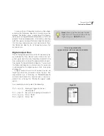
The signal input is at pin 4 with the ground refer-
ence on pin 2. Pin 2 is connected to the outer shield for
the connector, but it is recommended to separate the
shield from the signal reference since the instrument
has a very low self noise and ground currents can eas-
ily destroy low level signals in the microvolt range.
When you select the standard preamplifier by
pressing
SETUP
>
1
>
4 (
Press
INC
if “STANDARD”
is not displayed), the signal input is an AC-coupled
input terminal with an input impedance of more than
600 k
Ω.
This mode is used when the ordinary preamp-
lifier Nor1209 is applied.
The signal terminal may also be used for more gen-
eral applications as for measuring the AC-voltage from
other transducers or sources. The measurement range
is from ± 10 volt peak to levels less than a microvolt
– dependent of the applied frequency weighting. The
cable Nor1438 with a BNC connector in the far end
may be convenient for such applications.
In this case you should set the input from
STANDARD
to
LINE
.
IEPE
The input terminal pin 4 may also supply current to
transducers of the constant current or IEPE-type. This
mode is selected by pressing
SETUP
>
1
>
4
and
toggle the input to IEPE. A current of 3 mA from
a 25 volt power source will then be supplied to a
connected transducer. These types of transducers are
often used for measurement of acceleration. Nor140 is
able to measure down to 0,4 Hz, and will therefore be
well suited for such applications.
If you need a very long extension cable between
the microphone and the instrument, you should
consider the Nor1207 IEPE-type of preamplifier. This
will allow a one-conductor, screened cable to be used.
Nor1207 may be delivered with either BNC or TNC
output connector.
A detailed description of the input menu is given on
page 15.
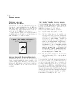
p2
p3
p7
p5
p6
p1
p4
Summary of Contents for nor140
Page 4: ......
Page 16: ......
Page 17: ...nor140 SOUND ANALYSER ...
Page 18: ......
Page 212: ...194 ...
Page 218: ......

