87
Norsonic Nor140
Instruction Manual
External trigger
The external trigger function is selected by moving
the field cursor to the field “External” and pressing
ENTER
.
After pressing the
START
key, the instrument will
start waiting for an externally supplied binary voltage
signal (3,3 volt CMOS). The signal has to be applied
to DI-1, pin no 8 on the general I/O-socket. See the
specification section for further information.
The remote hand switch Nor263A is designed for
external trigger of either remote start of the meas-
urement process or remote start of an audio record-
ing. The trigger conditions is set in the trigger menu;
SETUP
>
6
. After selecting the trigger condition the
digital IO must be configured to use the remote hand
switch Nor263A. You may skip the configuration, since
the push button will work regardless of the setting.
However, to achieve proper operation of feedback LED
mounted on the handswitch, you need to set this in the
digital IO menu. Push
SETUP
>
1
(Instrument menu) >
2
(IO / Print) >
1
(Digital I/O). The LED is connected to
DO-1. Please note that the QC (Quality Control) func-
tion in the Reference Curve menu
SETUP
>
4
(Freq
mode) >
1
(Reference curve) must be turned off, un-
less is DO-1 and DO-2 reserved for the QC function.
Select DO-1 to RUN if you use the hand switch to
start a measurement or to
REC
if you use the hand
switch to start an audio recording.
If you set the repeat measurement function (Press
SETUP
>
1
>
1
), the instrument will start a new meas-
urement after the first is finished and wait for the trigger
condition to be satisfied again.
If you want to interrupt a waiting-for-trigger opera-
tion, press the
STOP
key.
Level above-trigger
The level above-trigger function allows a measure-
ment to be started as soon as the level in the specified
network or filter band is above a specified threshold.
In this way, a noise event may initiate a measurement.
The duration and time resolution of the measurement
are set as usual. The selected main time constant, F, S
or I, is used for the level triggering function.
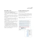
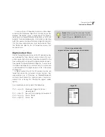
Move the field cursor to the field “Lvl.above” as
shown on the figure and press
1
for selecting the
threshold. A menu as shown on the right is displayed.
The field below “Threshld:” indicates the sound pres-
sure level needed for triggering. Modify the value by
using the
INC
and
DEC
key on the right side of the
display, or key in a numeric value followed by pressing
ENTER
.
When the required level is set, move the field cur-
sor to the field below “Freq/netw:”. Select the required
frequency band or network by using the
INC
and
DEC
key on the right side of the display. The networks
may be selected by scrolling above the highest fre-
quency band.
Press
ENTER
repeatedly until the main measure-
ment display appears.
For making a measurement, press the
START
key. A
“Wait-indicator”
will be shown in the display instead of the “Run-indica-
tor”. As soon as the level comes above the threshold,
the measurement is automatically started.
Summary of Contents for nor140
Page 4: ......
Page 16: ......
Page 17: ...nor140 SOUND ANALYSER ...
Page 18: ......
Page 212: ...194 ...
Page 218: ......


