127
Norsonic Nor140
Instruction Manual
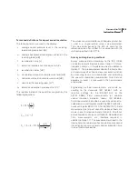
V
is the volume of the room
T
is the reverberation time of the room.
If your Nor140 is equipped with the optional extension
9 reverberation time measurements, you may use this
to calculate the absorption as follows:
K
2A
= 10log[1 + 4S/A] [dB]
K
2A
= 10log[1 + 4(S×T)/(0.163×V)] [dB]
based on an actual reverberation time measurement.
Test room qualification requirements
For the measurement surface in a test room to be sat-
isfactory for measurements in accordance with the re-
quirements of ISO 3746, the ratio of the sound absorp-
tion area
A
to the area
S
of the measurement surface
shall be equal to or greater than 1, that is A/S
≥
1. The
larger the ratio
A/S
is, the better.
If you cannot meet this requirement, a new meas-
urement surface shall be chosen. This surface shall
have a smaller total area, but shall still lie outside the
near field.
Alternatively you may improve the
A/S
by adding
sound-absorbing materials to the test room.
If this does not help, the test room cannot be used
for ISO 3746 measurements!
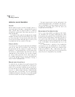
Measuring the sound power
The sound power calculation extension enables you to
make a complete sound power measurement, result-
ing in an L
W
a
value (the A-weighted sound power level)
of any test object in accordance with ISO 3746 and re-
lated Standards. This means that when equipped with
a Nor140 you may test the L
W
a
of new products for the
European labelling in the production area (
in-situ
),
rather than in a laboratory (
in-vitro
).
Making measurements
Before you start to make sound power measurements
we recommend that you familiarise yourself with how
to make regular sound level measurements.
Then do as follows:
1
Once the test object is properly placed, start
the setup procedure by selecting measurement
duration as described in
Making simple sound
measurements.
2
Press
SETUP
followed by
4
. The instrument will
now enter the measurement control display.
3
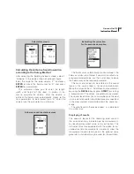
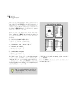
The Nor140 allows 1–40 microphone posi-
tions to be measured. The initial measurement
control display shows 8 positions, but this may
be extended to further pages covering the
positions 9–40 by pressing the key (“next
page”).
4
At the bottom of the screen, the averaged
sound pressure level based on the measured
microphone positions, is displayed. Each mi-
crophone position is selected by moving the
field cursor using the or keys to the selected
position, and then pressing the
START
key. The
screen will show the normal measurement dis-
play during a measurement, and return to the
control screen and display the measured L
EQ
a
value for the measured positions at the end of
each measurement.
Summary of Contents for nor140
Page 4: ......
Page 16: ......
Page 17: ...nor140 SOUND ANALYSER ...
Page 18: ......
Page 212: ...194 ...
Page 218: ......


