53
Installation
Nortec EL
2582302_C_EN_1611
5.8.3.11 Modbus Connection
The Nortec EL steam humidifier comes standard with a Modbus communications interface, which can
be used to remotely control its output or monitor its operation.
Refer to
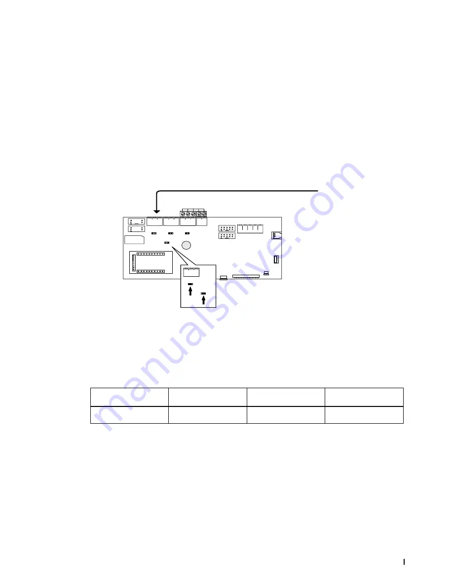
Figure 36
and connect the Modbus communication cable to the Nortec EL steam humidifier as
follows:
1. Connect a Modbus cable to the connector J6 on the Nortec EL control board. Refer to
Table 9
for
Modbus cable requirements, and
Table 10
for communication parameters. Contact your Nortec rep
-
resentative if assistance is needed to change the default communication parameters.
Note:
The
jumper JP7 on the control board must be installed to activate Modbus or BACnet MSTP
communication via RS485 interface (J6). If the jumper is not installed, no communication will take
place through J6.
2. Install the
jumper JP4 on the control board if the Nortec EL steam humidifier is the first or last unit in
the network. Termination is generally not required if the network is less than 3280 ft (1000 m) in length.
Figure 36:
COMM PORT
JP11
JP8
JP4
JP7
DISPLAY
DISPLAY
LED
BAT
+
-
+
-
+
-
J17
J18
J22
J23
J21
J19
GND
GND
GND GND 24V
CR2032
GND 5V 3.3V
RD
TD
SIM Card
Main Unit
USB
Ethernet
J3
ACC
J2 RFB
CONTROL
BOARD
JP4
JP7
+
-
GND
ACC
RF
B
J12
J14
J10
J6
J2
J3
J6
Modbus Connection on Nortec EL steam humidifier
JP4 Jumper for activating the termination resistor for Modbus or BACnet MSTP network
J6 Modbus connector (RS485 interface)
JP7 Jumper for activating Modbus or BACnet MSTP communication via RS485 interface (J6)
Table 9: ModBus Cable Requirements
BMS Protocol
Signal Type
Recommended Cable
Maximum Distance from
Nortec humidifier to BMS
Modbus
EIA-485, 2-wire
18-24 AWG shielded, twisted
pair, 120Ω *
2200 ft (670 m)
* Connect humidifiers in a daisy chain to the Modbus RTU. Ground shield at on end only – either at the BMS or the humidifier.


