


10-00
Page 2
2008-02-02
(1) FIELD INSTALLATION OF A SE-50 SERIES NORTEC LINKS 2 REMOTE
PACKAGE
A. STEP 1 - INSTALLATION
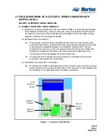
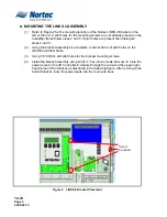
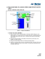
(1) Mount the LINKS 2 remote package in a convenient location. Note that the remote
package does not need to be mounted in close proximity to the humidifier.
(2) Connect power to the 24VAC and GND terminals of the LINKS 2 terminal strip. This
may be done in two ways:
(a)
A 120VAC to 24VAC plug-in transformer with screw terminals on the secondary
side has been supplied with this kit. Wire the transformer to the 24VAC and
GND terminals on the LINKS 2 terminal strip.
(b)
Connect power from the humidifier terminal strip (see wiring diagram for
details).
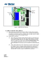
NOTE on 2(b)
Power to LINKS 2 module will be lost when the humidifier is switched off.
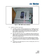
(3) Connect the slave humidifiers (if applicable) to the Nortec Links Module. A twisted
pair cable should be used so that the Net + terminal on the Links module should
connect to the first pin (bottom-most pin) of the TB3 connector. The Net – terminal on
the module should be connected to the second pin of the TB3 connector. Refer to
the unit’s wiring diagram for more information.
A. STEP 2 – CONFIGURING THE HUMIDIFIERS
NOTE
If the LINKS 2 remote package was shipped with the humidifiers, this step will have
already been performed by the factory.
(1) Since Nortec LINKS 2 can connect to a maximum of 8 units, it will be necessary to
set the unit address for each humidifier. The lead unit can be determined by the
presence of the LINKS 2 module. The slave humidifiers can be given a unit address
according to the number the unit will have on the networked chain.
(2) To set the network address access the User Parameter level in the humidifier
software menu. Scroll down to Modbus Settings and press enter.
(3) In order to change the current modbus address, press the up and down arrows on
the keypad at the same time. When prompted, enter the code 0335.
(4) Once the password is set select the modbus address heading and press enter. Use
the up and down arrows to change the address setting.
(5) Determine the desired humidifier ordering on the network. To change the network
instance follow step 3 and enter the parameter value of 2 for unit 2, 3 for unit 3 and
soon.
Summary of Contents for GSTC
Page 4: ...10 00 Page 1 2008 02 02 10 00 LINKS 2 FIELD INSTALLATION OF A SE 50 ...
Page 6: ...10 10 Page 1 2008 02 15 10 10 LINKS 2 FIELD CONVERSION OF A GSTC SETC ...
Page 10: ...10 20 Page 1 2008 02 15 10 20 LINKS 2 FIELD CONVERSION OF A NHTC ...
Page 14: ...10 30 Page 1 2008 02 15 10 30 LINKS 2 FIELD CONVERSION OF A NHDI SC ...