The Nortec MHTC / MHB |
8
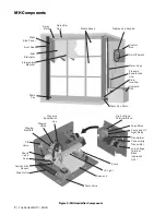
Description of Components
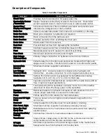
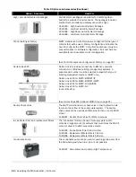
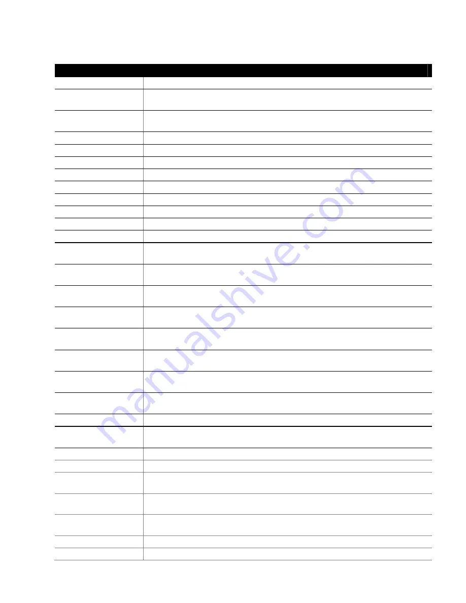
Table 2: Humidifier Components
Component
Function of Component
Check Valve
Provides back flow protection for supply water line.
Conductivity Sensor
/Transmitter
Sensor measures conductivity of water in the reservoir. Transmitter
sends measured value to control box for use in water quality control.
Control Box /
Display and Keypad
Controls all functions of the humidifier’s operation and provides user
interface for configuration of the humidifier.
Drain Pan
Collects unevaporated water from media for recirculation or draining.
Drain Pan Drain
Drain pan connection to hydraulic unit reservoir.
Drain Outlet
Drain connection from the hydraulic unit.
Drain Overflow
Provides protection from overfilling the drain pan.
Drain Valve
Drains water from the reservoir.
Duct Seal
Prevents duct air flow from bypassing the humidifier.
Fill Valve
Controls makeup water flow to humidifier based on float level.
Float
Measures water level in reservoir to prevent over filling.
Fuse Block
Overcurrent protection for pump and UV light.
High Voltage
Terminal Block
Primary voltage connection on hydraulic unit and in control box.
Hydraulic Unit
Collects water from the drain pan and pumps, treats with UV light, and
stages water to media. Fills and drains reservoir to control water quality.
Intermediate
Member
Structural member supports media boxes.
Low Voltage
Terminal Block
Hydraulic Unit – connects control box inputs to the hydraulic unit.
Control Box – provides connection for control signals and safety loop.
Media Boxes
Surface from which water is evaporated for humidification/cooling.
Available in 8 in. (20 cm) or 12 in. (30 cm) thickness.
Mist Eliminator
Captures any water droplets that are carried off the media boxes with air
flow in high duct speed applications.
On/Off Switch
Turns power On/Off to humidifier controller. Note: Turn off humidifier
disconnect to shut off primary power to the humidifier.
Pressure
Equalization Line
Balances pressure in hydraulic unit reservoir with pressure in duct to
ensure proper water flow to reservoir from drain pan.
Pump
Pumps water from the reservoir to the media boxes.
Pump and UV Light
Relay
Turns on power to the UV light and pump based on signal from the
control box.
Reservoir
Collects water from the drain pan for recirculation / draining.
Side Panel, Right
Structural member supports media boxes and spray bar cap.
Spray Bar Cap/
Spray Bars
Distributes water to the media boxes and prevents water from spraying
anywhere else.
Staging Manifold /
Valve(s)
Controls flow of water to media boxes based on demand.
Transformer
Steps primary voltage down to 24 VAC for the controller and internal
components such as the fill valve and drain valve.
UV Light
Eliminates any bacteria in the water being pumped to the media boxes.
Water Lines
Supply water lines from hydraulic unit to spray bars.
Summary of Contents for MH Series
Page 45: ...MH Installation Requirements 42 ...
Page 46: ...43 Warranty ...


