background image


NH 

Series


Installation and 

Operation Manual 

Includes installation, operation 
maintenance and troubleshooting 
information for your NHRS Resistive 
Element Steam Humidifier 


2530618-

*

 | 08 SEP 2010 

Important: 

Read and save these instructions. This guide to be left with equipment. 

Summary of Contents for NH Series

Page 1: ...ion Manual Includes installation operation maintenance and troubleshooting information for your NHRS Resistive Element Steam Humidifier 2530618 08 SEP 2010 Important Read and save these instructions This guide to be left with equipment ...

Page 2: ...xcept to the extent required for installation or maintenance of recipient s equipment All references to the NORTEC name should be taken as referring to WALTER MEIER LTD Liability Notice NORTEC does not accept any liability for installations of humidity equipment installed by unqualified personnel or the use of parts components equipment that are not authorized or approved by NORTEC Copyright Notic...

Page 3: ...BUTOR INSTALLATION FOR THE ASD BSD CSD 27 3 SAM E SHORT ABSORPTION MANIFOLD 33 4 BLOWER PACKS BOBP RMBP 41 10 20 OPERATION 1 OPERATION 46 2 NHRS OPERATION 47 10 30 MAINTENANCE PROCEDURES 1 NHRS MAINTENANCE 62 10 40 TROUBLESHOOTING 1 TROUBLESHOOTING 68 2 START UP CHECK LISTS 72 3 MAINTENANCE CHECK LISTS 75 10 50 TECHNICAL 1 EXPLODED VIEWS PLUMBING 78 2 EXPLODED VIEWS ELECTRICAL 80 WARRANTY ...

Page 4: ......

Page 5: ...l code Electrical connection to be performed by a licensed electrician CAUTION Plumbing Plumbing to be performed by a licensed plumber Drain water from humidifier can be very hot Do not drain to public sink All plumbing work should be done according to local plumbing code CAUTION Installation Do not mount on hot surfaces Do not mount in area where freezing can occur Do not mount on vibrating surfa...

Page 6: ...Page 1 10 00 INTRODUCTION ...

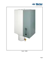
Page 7: ...Page 2 Figure 1 NHRS ...

Page 8: ...rectly to the shipping company 2 PACKAGING A GENERAL 1 The equipment packaging is standardized in that each box will contain the same base content The following paragraphs identify the content of each box B HUMIDIFIER AND CONTROL BOX 1 The typical equipment found in the humidifier and control box are shown in Figure 2 The contents are listed on the box If controls and any other small accessories a...

Page 9: ...STICKERS CONTROLS IF ORDERED ONLY BAG WITH MANUAL CLAMPS HOSE SECTION HUMIDIFIER STEAM HOSE SECTION NOT SUPPLIED IF BUILT ON BLOWER PACK ORDERED Figure 2 Humidifier Box Figure 3 Distributor Box Figure 4 SAM e Distributor Box Figure 5 Remote Mounted Blower Pack Box ...

Page 10: ...e humidifier s specification label 2 Ensure that the external fuse disconnect is sufficient size to handle the rated amperage as indicated on the humidifier s specifications label Refer to local building codes 3 Report any discrepancy immediately to the site engineer 4 Location and mounting is described in Chapter 10 10 5 For typical installation see Figures 6 7 ...

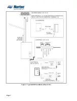
Page 11: ...Page 6 Figure 6 Typical NHRS Installation Sheet 1 of 2 ...

Page 12: ...Page 7 Figure 7 Typical NHRS Installation Sheet 2 of 2 ...

Page 13: ...Page 8 THIS PAGE INTENTIONALLY LEFT BLANK ...

Page 14: ...Page 9 10 10 INSTALLATION PROCEDURES ...

Page 15: ...ng B MOUNTING 1 The NHRS series humidifier is wall mounted using keyholes located on the back of the unit s cabinetry The keyholes are spaced 16 inches apart center to center as per UL certification standard stud spacing dictates 2 Use 12 x 3 in screws 2 screws are needed for a single unit NHRS 010 to 090 lbs hour 3 screws are needed for a double unit NHRS 135 to 180 lbs hour Insert the screw 16 i...

Page 16: ...cing Use 1 2 in outside diameter copper piping to the humidifier See Figure 1 for further detail D WATER SUPPLY LINE De ionized Water Supply 1 All water supply and drain line connections should be installed in accordance with local building codes 2 It is always recommended to install a manual shut off valve on the fill water supply line dedicated to the humidifier to facilitate servicing Use 1 2 i...

Page 17: ...Page 12 Figure 1 Plumbing Connections ...

Page 18: ...or siphoning from occurring It is recommended to place this air gap as close to the unit as possible to limit any chance of siphoning A copper funnel should be used reducing the drain line to a minimum of 2 in O D pipe If DI or RO water is used stainless steel is recommended for the drain line and funnel Purified water will deteriorate copper over time and use See Figure 1 for further detail 4 The...

Page 19: ...nk Bracket 1 Line up holes in bracket with holes in drain pan Fasten the bracket to the drain pan using the four 10 32 nylon lock nuts 2 Fasten the front of the bracket with the two 10 24 self tapping screws provided 3 The two locking screws for the bracket should already be installed ...

Page 20: ...oth mechanisms by rotating counter clockwise until opening is visible 3 Place scale tank on support bracket 4 Rotate bracket to close mechanism and raise scale tank Note ensure scale tank lines up with opening at the bottom of the drain pan when raising 5 Lock mechanism by re inserting the two locking screws ...

Page 21: ... mentioned are equivalent feet and therefore the full length of steam line includes the addition of the equivalent length of all elbows and tees 2 Figure 4 and Figure 5 illustrates the guidelines for installation routing and trapping of the steam lines and condensate returns 3 Table 6 indicates steam outlet size of the humidifier and steam inlet size of the distributor ...

Page 22: ...or DI Short Run 10 feet 3m yes yes yes Long Run 10 feet 3m no yes yes NOTE Long runs affect accuracy of humidifier and its ability to quickly respond to changes in demand when tight control is required Table 3 Recommended Materials and Sizes for Steam Runs Unit Size Steam Run Steam Line Material Steam Line Description lbs hr kg hr ft m Potable 0 30 0 13 0 10 0 3 Copper Tube 1 500 in MED L Tubing 1...

Page 23: ...Page 18 Figure 4 Steam Run and Condensate Return Installation Guidelines 1 of 2 ...

Page 24: ...Page 19 Figure 5 Steam Run and Condensate Return Installation Guidelines 2 of 2 ...

Page 25: ...condensate line must be trapped before it is joined together See figure 4 Table 5 Equivalent Lengths of Elbows and Tee Fittings Nominal Tube Diameter Standard 90degree Elbow Standard 45 degree Elbow Side Outlet Tee 0 75 inch 2 feet 1 foot 4 feet 1 5 inch 3 5 feet 1 75 feet 7 feet 3 inch 5 feet 2 5 feet 11 feet 4 inch 8 feet 4 feet 15 feet Table 6 Humidifier and Distributor Inlet Outlet Sizes Humid...

Page 26: ...sories If controls were not ordered with the humidifier they must be purchased or supplied by others The following information is relevant to all controls factory supplied or otherwise I DEMAND SIGNAL CONTROLS INSTALLATION 1 Figure 8 uses the NORTEC optional controller to demonstrate the typical demand signal installation J HUMIDITY TRANSDUCER SIGNAL INSTALLATION 1 Figure 10 displays NORTEC option...

Page 27: ...ANY TWO LEGS LOAD WILL BE BALANCED L3 NEUTRAL PRIMARY LINE VOLTAGE WIRING TO UNIT E X T I N T E X T I N T E X T I N T DEDICATED CIRCUIT BREAKER ORFUSED DISCONNECT DEDICATED CIRCUIT BREAKER ORFUSED DISCONNECT BYOTHERS ON OFF ADEDICATEDEXTERNALFUSED DISCONNECTMUSTBE INSTALLED DONOTEXCEED THEMAXIMUMCIRCUIT PROTECTIONAMPSAS INDICATEDONTHE LABEL SPECIFICATION ENSURETHATADEQUATEPOWERSUPPLYIS AVAILABLETO...

Page 28: ...Page 23 Figure 7 On Off Guidelines and Low Voltage Terminal Strip 254 8731 ...

Page 29: ...Page 24 Figure 8 NORTEC Control Guidelines and Wiring Optional ...

Page 30: ... on the humidistat controller enables this Outdoor Temperature Setback option The Outdoor Temperature Sensor is then wired to these terminals 3 When the outdoor Temperature setback feature is in effect the humidistat will normally display the calculated setpoint limit based on the outdoor air temperature A snowflake will also be displayed to indicate cold weather operation When any key on the cont...

Page 31: ...Page 26 Figure 10 NORTEC Humidity Transducer Guidelines and Wiring Option ...

Page 32: ...tle at the bottom of the steam distributor where it is removed by the condensate return 2 Ensure the total capacity of the humidifier is not higher then the allowable maximum steam capacity of the following distributors a ASD 25 lbs hour 9 kg hour b BSD 35 lbs hour 13 kg hour c CSD 115 lbs hour 45 kg hour C DISTRIBUTOR LOCATIONS AND MOUNTING 1 NORTEC distributors can be mounted in air handlers sup...

Page 33: ... FACTORY FOR HIGHER VELOCITY CAUTION PLEASE MAKE SURE THAT NO OBSTACLES ELBOW FILTER OR DIFFUSER ARE LOCATED AFTER THE DISTRIBUTOR IN THE DIRECTION OF AIRFLOW CLOSER THAN THE ABSORPTION DISTANCE CALCULATED FOR YOUR APPLICATION CAUTION UNLESS YOU KNOW THE EXACT ABSORPTION DISTANCE REQUIRED FOR THE STEAM ABSORPTION INTO THE AIR STREAM THE DISTRIBUTOR SHOULD BE LOCATED AT LEAST 8 10FT 2 3M AWAY FROM ...

Page 34: ...Page 29 Figure 11 Leveling the Distributor Figure 12 Single Steam Distributor Figure 13 Multiple Steam Distributor W W ...

Page 35: ...ches additional duct height for each additional ASD ROUNDDOWN Duct height 8 inch 5 inches 1 b BSD 10 in vertical duct height for the 1st BSD 6 inches additional duct height for each additional BSD ROUNDDOWN Duct height 10 inch 6 inches 1 c CSD 14 in vertical duct height for the 1st CSD 9 inches additional duct height for each additional CSD ROUNDDOWN Duct height 10 inch 9 inches 1 ...

Page 36: ...um of 8 in from the heating coil and evenly spaced If downstream wetting is a problem add more distributors See Figure 15 F DISTRIBUTOR ABSORPTION DISTANCE 1 The water vapor discharged from the steam distributor must be adequately mixed with air to prevent condensation on downstream components Consult the designing engineer or refer to the NHRS Engineering Manual G TYPICAL APPLICATIONS 1 Represent...

Page 37: ...Page 32 Figure 15 Best Location for Multiple Steam Distributors Figure 16 Roof Top Units 2 20 Tons Typical Location Figure 17 Small Unit on Residential Furnace ...

Page 38: ...flush with the rubber gasket See Figure 16 Make sure that all nozzles offset each other by rotating the tubes See Figure 17 NOTES Appling water to the gasket will help to slide the tube into place Do not lift the manifold by the steam tube when installing i Fasten the top steam tube bracket to secure all steam tubes using a bolt washer and nut assembly Factory Supplied See Figure 20 ii Fasten top ...

Page 39: ... in bolt washer and nut assembly Factory Supplied c Fasten side frame to the base of the manifold with 0 375 in bolt nut and washer assembly Field Supplied d Fasten pivoting head to the top of the duct using bolt nut and washer assembly Field Supplied NOTES Appling water to the gasket will help to slide the tube into place Do not lift the manifold by the steam tube when installing ...

Page 40: ...Page 35 Figure 18 SAM e Tubes Figure 19 Steam Tube Offset Figure 20 Top Steam Tube Bracket Figure 21 Adjustable Mounting Frame ...

Page 41: ...Page 36 Figure 22 Typical SAM e Duct Installation ...

Page 42: ... offset each other by rotating the steam tubes See Figure 19 NOTES Applying water to the gasket will help slide the steam tube into place Do not lift the manifold by the steam tubes when installing Optional cover plate to seal openings see Figure 23 and Table 6 c Slip steam tubes into the duct d Drill 4 x 0 500 in 12 7mm holes into the duct to match the header mounting brackets e Fasten the header...

Page 43: ...r assembly Field Supplied C VERTICAL IN DUCT INSTALLATION NOTE Mounting Frame Required See Figure 24 1 Once you have selected the location of the manifold use the supplied template to cut out the holes for the steam inlet and condensate drain outlet 2 Reverse the direction of the header mounting bracket to accommodate a 10 minimum angle 3 Insert the sliding panel into the base of the SAM e 4 Faste...

Page 44: ...N INSTALLED THIS COULD DAMAGE THE GASKET 10 Insert all steam tubes into the main header Make sure all nozzles offset each other by rotating the steam tubes See Figure 19 a Applying water to the gasket will help slide the steam tube into place b Do not lift the manifold by the steam tubes when installing c Nozzles must be perpendicular to the airflow D DRAIN WATER COOLING OPTION a Figure 25 display...

Page 45: ...Page 40 Figure 25 SAM e Drain Water Cooling ...

Page 46: ...red to the humidifier RMBP or separate power source See Figure 26 3 Blower packs consist of a steel cabinet containing 3 axial blowers with finger guards powered by 120VAC or line voltage humidifiers built in multi tap transformers when necessary fuse high temperature plastic distributor with stainless steel lid horizontal and vertical adjustment knobs for directional control built in thermostat t...

Page 47: ...72 183 045 1 36 91 84 213 065 1 2 42 106 144 366 090 1 2 48 122 156 396 135 2 4 42 106 144 366 180 2 4 48 122 156 396 NOTES 1 Clearances based on 72 F 35 relative humidity 2 Remote mounted blower packs must be used for NHRS 3 When there are clearance restrictions adding blower packs may resolve the problem For example using 2 x 045 blower packs instead of 1 x 090 blower pack the ceiling clearance ...

Page 48: ...p of the humidifier To access the blower pack terminal strip you must remove the cover The primary voltage can come from a remote source as well NOTES Terminal block are pre installed on units order with a remote mounted blower pack Otherwise the terminal block will be provided Class 1 circuit wiring is require between humidifier and blower pack 4 Field wiring of remote mounted blower pack must co...

Page 49: ...Page 44 THIS PAGE INTENTIONALLY LEFT BLANK ...

Page 50: ...Page 45 10 20 OPERATION ...

Page 51: ...shed on and all control options are calling A primary to 24 volt step down transformer provides power to the contactor holding coil s via the main control board The humidifier s operating status is reported to the user by the green red and yellow indicator lights on the front of the unit 4 The prerequisites for getting power and water into the steam cylinder are as follows a On off switch must be ...

Page 52: ... a time dependent process at pre selected time intervals c Pre determined time intervals are selected based on the water quality and the operating data 2 The minerals precipitated by the evaporation process accumulate at the bottom of the steam cylinder Units configured with the scale management option designed for operation with untreated water are equipped with a scale collector tank located dir...

Page 53: ... carries out a system test The display below appears and the three LEDs light for approx 3 seconds NOTES If a fault is detected during the system test a corresponding fault message is triggered If the system test is successful the steam cylinder fills up and a float test is carried out function check on the level unit The display below appears NOTES If a fault is detected during the float test a c...

Page 54: ...y network 4 Set the desired humidity value on the humidity controller humidistat 5 Make sure no leaks are present NOTE The heating current switches on as soon as the humidity controller humidistat demands humidity The yellow LED lights and steam is produced after a short delay approx 5 minutes 2 The operating status is displayed in the LED on the unit as follows Table 1 NHRS Operational Status LED...

Page 55: ...erating and fault indication option RFS the operating status will be shown as follows Table 2 Remote Fault Indication K1 Steam N O Normally open K2 Error N O Normally open Or N C Normally closed K3 Service N O Normally open Or N C Normally closed K4 Unit On N O Normally open ...

Page 56: ...ividual operating parameters that can be selected using the keys and after the display level has been called up a Steam Production 1 Current actual and nominal value of steam production are displayed in percentage of total output 2 Nominal value Unit capacity x input signal value 3 Actual value max Unit capacity x input signal value x capacity limitation NOTE If the internal controller is activate...

Page 57: ...cer signal 3 Demand de activated d Working Hours 1 Total of working hours elapsed since initial commissioning of the steam humidifier e Time Remaining to minor major service 1 The time remaining in hours before the next minor major service NOTE Time to maintenance can be adjusted to suit water conditions NOTE The stated times are based on 100 steam capacity If the operation is at a lesser capacity...

Page 58: ... 6 500 hours 1500 hours 7 750 hours 1500 hours 8 3000 hours 3000 hours 9 6000 hours 6000 hours Position S2 Interval Minor Maintenance Interval Major Maintenance 10 0 15 0 20 0 30 0 45 0 6 0 90 0 135 0 180 0 S2 Setting NHRS Model Value Setting Factory Setting NHRS Main PCB Maintenance Interval Adjustment S2 Figure 1 NHRS Maintenance Intervals ...

Page 59: ... following indications are provided for the set flushing interval Left Switch setting on rotary switch S1 4 in example Right Set flushing interval 120 in example NOTE The flushing interval is set on switch S1 on the control board ...

Page 60: ...Page 55 Figure 2 Drain Interval Settings ...

Page 61: ...s per gallon 0 grains per gallon Silica 12 ppm 0 ppm PH 6 5 7 5 7 Chlorides 50 ppm 25 ppm NOTE Should you have water conditions above the stated parameters consult the factory for a new blow down setting to help improve your scale management NORTEC recommends performing a semi annual water analysis to ensure optimal performance f Stand by Heating 1 Stand by heating activated on deactivated off NOT...

Page 62: ...orrection cycle ratio in of standard setting value to balance out water pressure variations i Soft Start 1 Soft Start activated on consult factory Deactivated off factory set j De mineral Mode 1 De mineral mode activated on consult factory Deactivated off factory set k Serial Interface 1 Serial Interface activated on consult factory Deactivated off factory set l Full Drain Cycle 1 Full Drain Cycle...

Page 63: ...Page 58 Figure 3 Control Signal Setting ...

Page 64: ...d off factory set m Control Signal 1 Range of the active analog signal in Volts or milliamps NOTE The range of the analog signal may be adjusted using the rotary switch S3 on the control board n Software Version 1 Displays software version for the steam humidifier o Unit Type ...

Page 65: ...Page 60 THIS PAGE INTENTIONALLY LEFT BLANK ...

Page 66: ...Page 10 30 MAINTENANCE PROCEDURES ...

Page 67: ...ctrical installation for lose or frayed cables as well as damaged components c Inspect the condition of the unit s cabinetry for damage d Survey the area surrounding the humidifier make sure all clearances are met 2 Maintenance a Manually drain the NHRS by pressing the drain button on the display b Turn the units power to the off position c Switch the external electrical disconnect to the off posi...

Page 68: ...raint j Lift the cylinder upward then out of the front of the unit CAUTION BE EXTREMELY CAREFULL WHEN HANDLING THE STEAM CYLINDER IF IT IS DROPPED AND DAMAGED THERE IS A GOOD CHANGE IT WILL NOT SEAL PROPERLY AND THE ENTIRE CYLINDER WILL NEED TO BE REPLACED k Remove the clamp at the top of the cylinder l Remove the tank lid with elements attached m Remove all scale from the tank n Inspect the heati...

Page 69: ...Page 6 Figure 1 Minor Maintenance with Scale Management Option ...

Page 70: ... that connect to the top of the steam cylinder NOTE The heating elements will not be affected if they are connected to different power lines from the electrical department 6 Using a slotted screwdriver loosen the gear clamps that hold the steam line in place 7 Remove the steam line 8 Remove the Zip Tie cylinder restraint 9 Lift the cylinder upward then out of the front of the unit CAUTION BE EXTRE...

Page 71: ...ess and hold the drain activation switch 3 Continue to hold the drain activation switch and turn the main power switch to the on position 4 Allow the unit to undergo the initial start up diagnostic when the diagnostic is complete release the drain activation switch The unit maintenance should be cleared at this point ...

Page 72: ...Page 6 10 40 TROUBLESHOOTING ...

Page 73: ...er temperature switch on steam cylinder is broken or over temperature switch faulty Steam cylinder overheating over temperature switch has responded Flat band cable between control and power board interrupted or not connected Check connections or replace over temperature switch Inspect steam cylinder clean if necessary Replace over temperature switch Inspect connections connect or replace flatband...

Page 74: ... line and siphon Clean or replace hose Invalid level Error code 6A 6B Alarm6A Levelindicat Error6B levelindicat Level unit faulty Magnetic field in vicinity of level unit Replace level unit Eliminate magnetic field Steam pressure error only Error code 7A 7B Alarm7A communication Steam hose blocked or restricted water trap Pressure balance adapter into steam connection fitting blocked Duct pressure...

Page 75: ...Page Figure 1 Wiring Diagram ...

Page 76: ...Page Figure 2 Wiring Diagram ...

Page 77: ...IFIER MOUNTING Clearances around the unit Acceptable Obstruction Front door opens freely 3ft min __________________ Top steam lines 1ft min ____________________ Bottom fill drain controls 1ft min ____________________ Right main pwr 3ft min ____________________ Left main pwr 2 min ____________________ Ensure the scale tank bracket is locked in place STEAM LINES CONDENSATE LINES Slope up 2 per 12 Sl...

Page 78: ...it or on the PC board Yes no CONTROLS Installed Location Wiring Setting High limit _________________ Air proving _________________ Mod controller _________________ Other _________________ POWER Voltage amperage rating and fuse corresponds to Spec Label Disconnect switch located close to humidifier Field contact ___________________________ Signature _______________________________ ...

Page 79: ...P PROCEDURE The prerequisites for getting power and water into the steam cylinder is as follows 1 Check that main breaker is on and power is at the unit 2 Check that main water shut off valve is open 3 on off switch must be switched on 4 Control circuit 1 2 must be made 5 Modulation humidistat if present must be calling 6 Door interlock switch must be made interlock switch can be pulled out to ope...

Page 80: ...__________________________________________ ____________________________________________________________________________________ ____________________________________________________________________________________ 3 MAINTENANCE CHECK LISTS Maintenance Checklist p 1 of 1 Unit Serial ____________ of humidifiers ____________ Tag _____________ Unit type NHRS Voltage _____V ___ph Steam output ____lbs hr...

Page 81: ...Page 7 THIS PAGE INTENTIONALLY LEFT BLANK ...

Page 82: ...Page 7 10 50 TECHNICAL ...

Page 83: ...Page 7 Figure 1 Exploded View Plumbing ...

Page 84: ...Page 7 Table 1 Exploded View Plumbing ...

Page 85: ...Page Figure 2 Exploded View Electrical ...

Page 86: ...Page Table 2 Exploded View Electrical ...

Page 87: ...o the original purchase price for the product Any further warranty must be in writing signed by an officer of THE COMPANY THE COMPANY s limited warranty on accessories not of the companies manufacture such as controls humidistats pumps etc is limited to the warranty of the original equipment manufacturer from date of original shipment of humidifier THE COMPANY makes no warranty and assumes no liab...

Page 88: ...venue Ogdensburg NY 13669 CANADA Walter Meier Climate Canada Ltd 2740 Fenton Road Ottawa Ontario K1T 3T7 TEL 1 866 NORTEC1 FAX 613 822 7964 EMAIL northamerica climate waltermeier com WEBSITE www humidity com www norteconline com Certificate No 002419 ...

Reviews: