


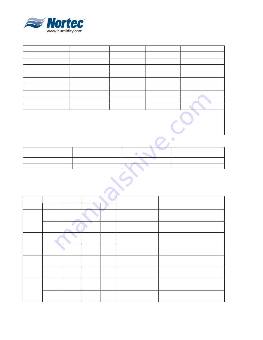
Page 17
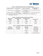
Table 1. Maximum Recommended Length of Steam Line
NHRS unit size
Steam Output
Distance
Possible Loss
Steam Line Size
010
10 lbs
15
2
1 ½”
015
15 lbs
17.5
2.25
1 ½”
020
20 lbs
20
2.5
1 ½”
030
30 lbs
25
3
1 ½”
045
45 lbs
35
4 to 5
1 ½”
065
65 lbs
45
5 to 10
1 ½”
090
90 lbs
50
5 to 10
1 ½”
135
135 lbs
50ft/cylinder
5 to 10
2 x 1 ½”
180
180 lbs
50ft/cylinder
5 to 10
2 x 1 ½”
Notes: 1. This chart gives the maximum length of recommended steam line by unit size.
2. The use of steam line other then copper, stainless steel and Nortec steam hose
will void the warranty and may cause adversely effect the operation of the
humidifier
3. The NHRS 135 and 180 are dual units.
Table 2. Steam Line Materials
NORTEC Steam Line
Copper Tube (Potable)
Stainless Steel Tube
(RO or DI)
Short Run < 10 feet (3m)
yes
yes
yes
Long Run > 10 feet (3m)
no
yes
yes
NOTE:
Long runs affect accuracy of humidifier and its ability to quickly respond to changes in demand when tight control is
required.
Table 3. Recommended Materials and Sizes for Steam Runs
Unit Size
Steam Run
Steam Line Material
Steam Line Description
lbs/hr
kg/hr
ft
m
Potable
0-30
0-13
0-10
0-3
Copper Tube
1.500 in MED-L Tubing
(1.625 inch OD)
0-30
0-13
10-30
3+
Copper Tube
2.0 inch MED-L Tubing
(2.125 inch OD)
RO or DI
0-30
0-13
0-10
0-3
Stainless Steel Tube
1.750 inch Tube x
0.065 inch thick
0-30
0-13
10-30
3+
Stainless Steel Tube
2 inch Tube x
0.065 inch thick
Potable
50-100
22-45
0-20
0-6
Copper Tube
1.500 in MED-L Tubing
(1.625 inch OD)
50-100
22-45
20+
6+
Copper Tube
2.0 inch MED-L Tubing
(2.125 inch OD)
RO or DI
50-100
22-45
0-20
0-6
Stainless Steel Tube
1.750 inch Tube x
0.065 inch thick
50-100
22-45
20+
6+
Stainless Steel Tube
2 inch Tube x
0.065 inch thick
Summary of Contents for NH Series
Page 4: ......
Page 6: ...Page 1 10 00 INTRODUCTION ...
Page 7: ...Page 2 Figure 1 NHRS ...
Page 11: ...Page 6 Figure 6 Typical NHRS Installation Sheet 1 of 2 ...
Page 12: ...Page 7 Figure 7 Typical NHRS Installation Sheet 2 of 2 ...
Page 13: ...Page 8 THIS PAGE INTENTIONALLY LEFT BLANK ...
Page 14: ...Page 9 10 10 INSTALLATION PROCEDURES ...
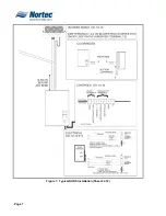
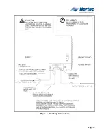
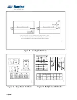
Page 17: ...Page 12 Figure 1 Plumbing Connections ...
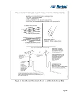
Page 23: ...Page 18 Figure 4 Steam Run and Condensate Return Installation Guidelines 1 of 2 ...
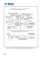
Page 24: ...Page 19 Figure 5 Steam Run and Condensate Return Installation Guidelines 2 of 2 ...
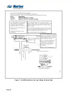
Page 28: ...Page 23 Figure 7 On Off Guidelines and Low Voltage Terminal Strip 254 8731 ...
Page 29: ...Page 24 Figure 8 NORTEC Control Guidelines and Wiring Optional ...
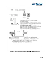
Page 31: ...Page 26 Figure 10 NORTEC Humidity Transducer Guidelines and Wiring Option ...
Page 41: ...Page 36 Figure 22 Typical SAM e Duct Installation ...
Page 45: ...Page 40 Figure 25 SAM e Drain Water Cooling ...
Page 49: ...Page 44 THIS PAGE INTENTIONALLY LEFT BLANK ...
Page 50: ...Page 45 10 20 OPERATION ...
Page 60: ...Page 55 Figure 2 Drain Interval Settings ...
Page 63: ...Page 58 Figure 3 Control Signal Setting ...
Page 65: ...Page 60 THIS PAGE INTENTIONALLY LEFT BLANK ...
Page 66: ...Page 10 30 MAINTENANCE PROCEDURES ...
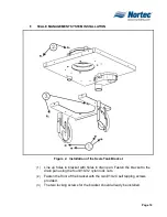
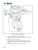
Page 69: ...Page 6 Figure 1 Minor Maintenance with Scale Management Option ...
Page 72: ...Page 6 10 40 TROUBLESHOOTING ...
Page 75: ...Page Figure 1 Wiring Diagram ...
Page 76: ...Page Figure 2 Wiring Diagram ...
Page 81: ...Page 7 THIS PAGE INTENTIONALLY LEFT BLANK ...
Page 82: ...Page 7 10 50 TECHNICAL ...
Page 83: ...Page 7 Figure 1 Exploded View Plumbing ...
Page 84: ...Page 7 Table 1 Exploded View Plumbing ...
Page 85: ...Page Figure 2 Exploded View Electrical ...