


Page 31
E.
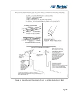
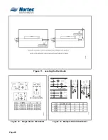
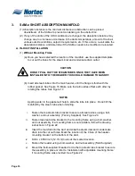
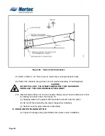
LOCATION OF STEAM DISTRIBUTORS WITHIN AN AIR HANDLER
(1)
Humidify after the heating coil (H/C) so that absorption will occur before the
cooling coil, any excess water will be drained away. There is little chance of
condensation on the blower, blower motor, or fan isolation components,
especially if you use a modulating high limit humidistat. All steam distributors
should be a minimum of 8 in. from the heating coil and evenly spaced. If
downstream wetting is a problem, add more distributors. See Figure 15.
F.
DISTRIBUTOR ABSORPTION DISTANCE
(1)
The water vapor discharged from the steam distributor must be adequately mixed
with air to prevent condensation on downstream components. Consult the
designing engineer or refer to the NHRS Engineering Manual.
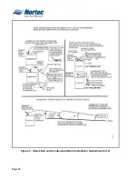
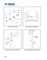
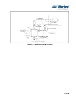
G.
TYPICAL APPLICATIONS
(1)
Representations of typical applications are found in Figure 16 and Figure 17
.
H.
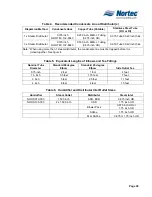
DISTRIBUTOR DIMENSIONS
(1)
Distributor dimensions for the various distributors can be found in the distribution
manual.
Summary of Contents for NH Series
Page 4: ......
Page 6: ...Page 1 10 00 INTRODUCTION ...
Page 7: ...Page 2 Figure 1 NHRS ...
Page 11: ...Page 6 Figure 6 Typical NHRS Installation Sheet 1 of 2 ...
Page 12: ...Page 7 Figure 7 Typical NHRS Installation Sheet 2 of 2 ...
Page 13: ...Page 8 THIS PAGE INTENTIONALLY LEFT BLANK ...
Page 14: ...Page 9 10 10 INSTALLATION PROCEDURES ...
Page 17: ...Page 12 Figure 1 Plumbing Connections ...
Page 23: ...Page 18 Figure 4 Steam Run and Condensate Return Installation Guidelines 1 of 2 ...
Page 24: ...Page 19 Figure 5 Steam Run and Condensate Return Installation Guidelines 2 of 2 ...
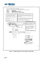
Page 28: ...Page 23 Figure 7 On Off Guidelines and Low Voltage Terminal Strip 254 8731 ...
Page 29: ...Page 24 Figure 8 NORTEC Control Guidelines and Wiring Optional ...
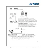
Page 31: ...Page 26 Figure 10 NORTEC Humidity Transducer Guidelines and Wiring Option ...
Page 41: ...Page 36 Figure 22 Typical SAM e Duct Installation ...
Page 45: ...Page 40 Figure 25 SAM e Drain Water Cooling ...
Page 49: ...Page 44 THIS PAGE INTENTIONALLY LEFT BLANK ...
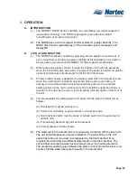
Page 50: ...Page 45 10 20 OPERATION ...
Page 60: ...Page 55 Figure 2 Drain Interval Settings ...
Page 63: ...Page 58 Figure 3 Control Signal Setting ...
Page 65: ...Page 60 THIS PAGE INTENTIONALLY LEFT BLANK ...
Page 66: ...Page 10 30 MAINTENANCE PROCEDURES ...
Page 69: ...Page 6 Figure 1 Minor Maintenance with Scale Management Option ...
Page 72: ...Page 6 10 40 TROUBLESHOOTING ...
Page 75: ...Page Figure 1 Wiring Diagram ...
Page 76: ...Page Figure 2 Wiring Diagram ...
Page 81: ...Page 7 THIS PAGE INTENTIONALLY LEFT BLANK ...
Page 82: ...Page 7 10 50 TECHNICAL ...
Page 83: ...Page 7 Figure 1 Exploded View Plumbing ...
Page 84: ...Page 7 Table 1 Exploded View Plumbing ...
Page 85: ...Page Figure 2 Exploded View Electrical ...