


Page 37
B. OUTSIDE DUCT INSTALLATION
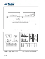
(1) WITHOUT MOUNTING FRAME
(a) Once you have selected the location of the manifold, cut out a 2 in. wide slot or a
2 in. diameter hole for each tube to be installed.
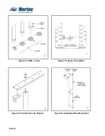
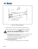
(b) Insert all steam tubes into the main header, until flange is flush with the rubber
gasket. See Figure 18. Make sure all nozzles offset each other by rotating the
steam tubes. See Figure 19.
NOTES
Applying water to the gasket will help slide the steam tube into place.
Do not lift the manifold by the steam tubes when installing.
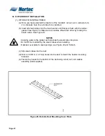
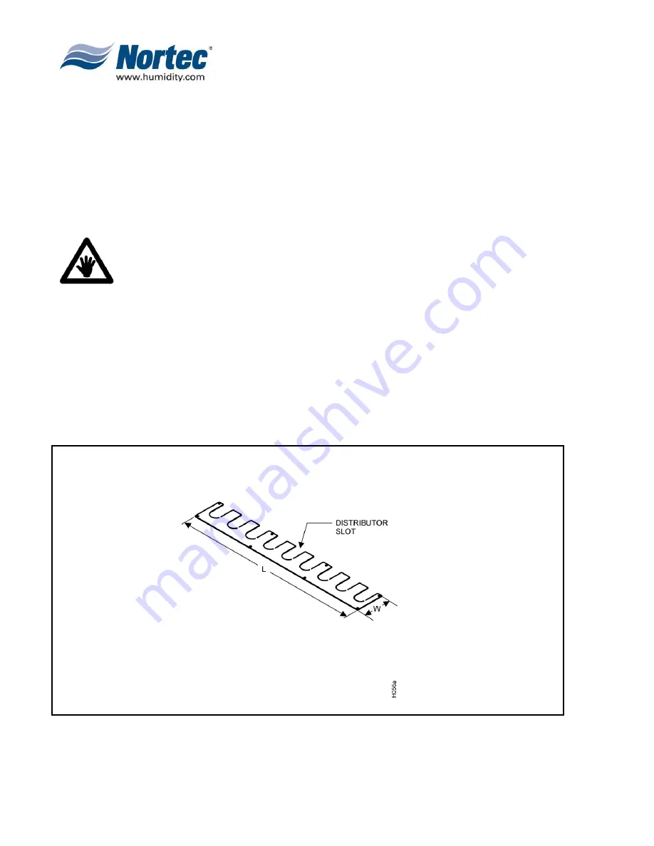
Optional cover plate to seal openings; see Figure 23 and Table 6.
(c) Slip steam tubes into the duct
(d) Drill 4 x 0.500 in. (12.7mm) holes into the duct to match the header mounting
brackets.
(e) Fasten the header to the bottom of the duct using a bolt, nut, and washer
assembly (field supplied).
Figure 23. Outside Duct Mounting Cover Plate
Summary of Contents for NH Series
Page 4: ......
Page 6: ...Page 1 10 00 INTRODUCTION ...
Page 7: ...Page 2 Figure 1 NHRS ...
Page 11: ...Page 6 Figure 6 Typical NHRS Installation Sheet 1 of 2 ...
Page 12: ...Page 7 Figure 7 Typical NHRS Installation Sheet 2 of 2 ...
Page 13: ...Page 8 THIS PAGE INTENTIONALLY LEFT BLANK ...
Page 14: ...Page 9 10 10 INSTALLATION PROCEDURES ...
Page 17: ...Page 12 Figure 1 Plumbing Connections ...
Page 23: ...Page 18 Figure 4 Steam Run and Condensate Return Installation Guidelines 1 of 2 ...
Page 24: ...Page 19 Figure 5 Steam Run and Condensate Return Installation Guidelines 2 of 2 ...
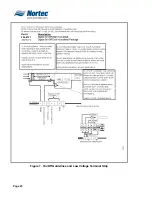
Page 28: ...Page 23 Figure 7 On Off Guidelines and Low Voltage Terminal Strip 254 8731 ...
Page 29: ...Page 24 Figure 8 NORTEC Control Guidelines and Wiring Optional ...
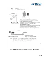
Page 31: ...Page 26 Figure 10 NORTEC Humidity Transducer Guidelines and Wiring Option ...
Page 41: ...Page 36 Figure 22 Typical SAM e Duct Installation ...
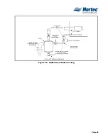
Page 45: ...Page 40 Figure 25 SAM e Drain Water Cooling ...
Page 49: ...Page 44 THIS PAGE INTENTIONALLY LEFT BLANK ...
Page 50: ...Page 45 10 20 OPERATION ...
Page 60: ...Page 55 Figure 2 Drain Interval Settings ...
Page 63: ...Page 58 Figure 3 Control Signal Setting ...
Page 65: ...Page 60 THIS PAGE INTENTIONALLY LEFT BLANK ...
Page 66: ...Page 10 30 MAINTENANCE PROCEDURES ...
Page 69: ...Page 6 Figure 1 Minor Maintenance with Scale Management Option ...
Page 72: ...Page 6 10 40 TROUBLESHOOTING ...
Page 75: ...Page Figure 1 Wiring Diagram ...
Page 76: ...Page Figure 2 Wiring Diagram ...
Page 81: ...Page 7 THIS PAGE INTENTIONALLY LEFT BLANK ...
Page 82: ...Page 7 10 50 TECHNICAL ...
Page 83: ...Page 7 Figure 1 Exploded View Plumbing ...
Page 84: ...Page 7 Table 1 Exploded View Plumbing ...
Page 85: ...Page Figure 2 Exploded View Electrical ...