


Page
38
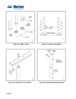
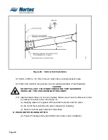
(f) Fasten the top of the steam tube bracket to secure all steam tubes using a bolt,
washer, and nut assembly. (Factory Supplied). See Figure 20.
(g) Fasten top steam tube bracket to side frame using bolt, washer, and nut
assembly.
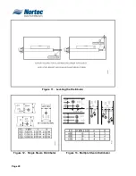
(h) Mount the field supplied rid to the top of the steam tube bracket to secure the
assembly in place. Refer to Figure 22.
(2)
INSTALLATION WITH ADJUSTABLE MOUNTING FRAME (Optional,
See Figure 21).
(a) Insert the sliding panel into the base.
(b) Fasten the pivoting head to the sliding panel with 0.375 in. UNC x 1 in. bolt,
nut, and washer assembly. (Factory Supplied).
(c) Mark the location of the 4 holes and drill 4 x 0.500 in. (12.7mm) holes
(d) Fasten the side frame to the base of the manifold with 0.375 in. UNC x 1
in. bolt, nut, and washer assembly. (Factory Supplied)
(e) Fasten the pivoting heads to the duct or air handler using a bolt, nut, and
washer assembly (Field Supplied)
C.
VERTICAL IN-DUCT INSTALLATION
NOTE
Mounting Frame Required. (See Figure 24.)
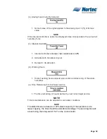
(1)
Once you have selected the location of the manifold, use the supplied template
to cut out the holes for the steam inlet and condensate drain outlet.
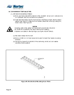
(2)
Reverse the direction of the header mounting bracket to accommodate a 10
minimum angle.
(3)
Insert the sliding panel into the base of the SAM-e.
(4)
Fasten the pivoting head to the sliding panel using 0.375 inch UNC x 1 in. bolt,
nut, and washer assembly. (Factory Supplied).
(5)
Mark the location of the 4 holes and drill 4 x 0.500 inch (12.7mm) holes.
(6)
Fasten the side frame to the base of the manifold with 0.375 inch UNC x 1 in.
bolt, nut, and washer assembly. (Factory Supplied).
(7)
Insert the manifold into the duct and slide the steam inlet and condensate drain
into the cut out holes. Mark the location of the 4 holes of the mounting brackets
and the 4 holes of the pivoting heads of the mounting frame to the sides of the
duct.
NOTE
Remember to keep a 10 angle to allow the condensate outlet to be at the lowest
point.
Summary of Contents for NH Series
Page 4: ......
Page 6: ...Page 1 10 00 INTRODUCTION ...
Page 7: ...Page 2 Figure 1 NHRS ...
Page 11: ...Page 6 Figure 6 Typical NHRS Installation Sheet 1 of 2 ...
Page 12: ...Page 7 Figure 7 Typical NHRS Installation Sheet 2 of 2 ...
Page 13: ...Page 8 THIS PAGE INTENTIONALLY LEFT BLANK ...
Page 14: ...Page 9 10 10 INSTALLATION PROCEDURES ...
Page 17: ...Page 12 Figure 1 Plumbing Connections ...
Page 23: ...Page 18 Figure 4 Steam Run and Condensate Return Installation Guidelines 1 of 2 ...
Page 24: ...Page 19 Figure 5 Steam Run and Condensate Return Installation Guidelines 2 of 2 ...
Page 28: ...Page 23 Figure 7 On Off Guidelines and Low Voltage Terminal Strip 254 8731 ...
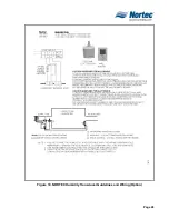
Page 29: ...Page 24 Figure 8 NORTEC Control Guidelines and Wiring Optional ...
Page 31: ...Page 26 Figure 10 NORTEC Humidity Transducer Guidelines and Wiring Option ...
Page 41: ...Page 36 Figure 22 Typical SAM e Duct Installation ...
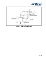
Page 45: ...Page 40 Figure 25 SAM e Drain Water Cooling ...
Page 49: ...Page 44 THIS PAGE INTENTIONALLY LEFT BLANK ...
Page 50: ...Page 45 10 20 OPERATION ...
Page 60: ...Page 55 Figure 2 Drain Interval Settings ...
Page 63: ...Page 58 Figure 3 Control Signal Setting ...
Page 65: ...Page 60 THIS PAGE INTENTIONALLY LEFT BLANK ...
Page 66: ...Page 10 30 MAINTENANCE PROCEDURES ...
Page 69: ...Page 6 Figure 1 Minor Maintenance with Scale Management Option ...
Page 72: ...Page 6 10 40 TROUBLESHOOTING ...
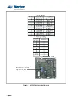
Page 75: ...Page Figure 1 Wiring Diagram ...
Page 76: ...Page Figure 2 Wiring Diagram ...
Page 81: ...Page 7 THIS PAGE INTENTIONALLY LEFT BLANK ...
Page 82: ...Page 7 10 50 TECHNICAL ...
Page 83: ...Page 7 Figure 1 Exploded View Plumbing ...
Page 84: ...Page 7 Table 1 Exploded View Plumbing ...
Page 85: ...Page Figure 2 Exploded View Electrical ...