


Page 43
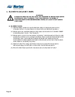
B. PRIMARY VOLTAGE CONNECTION
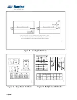
(1) All blower packs have high efficiency blowers to minimize the frontal and overhead
clearances required to absorb the steam.
(2) NH series remote mounted blower packs require field wiring between 2 primary
voltage terminal blocks and 2 low voltage control terminal strips; one of each is
located in the humidifier and the remote mounted blower pack cabinet. To properly
access the primary block on the humidifier, it may be necessary to remove the right
side panel. To connect the primary wiring and control wiring feed the wire though the
knockouts on the bottom and top of the humidifier. To access the blower pack
terminal strip you must remove the cover. The primary voltage can come from a
remote source as well.
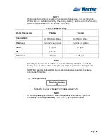
NOTES
Terminal block are pre-installed on units order with a remote mounted blower pack.
Otherwise the terminal block will be provided.
Class 1 circuit wiring is require between humidifier and blower pack.
(4) Field wiring of remote mounted blower pack must conform to national and local
electrical codes.
(5) For NH series use approved wire for power connections from 2 pole terminal block of
the remote mounted blower pack to additional 2 pole terminal block inside the
electrical section of the humidifier.
(6) For NH Series use approved wire to connect ground clamp of remote mounted
blower pack to ground clamp provided in the electrical section of the humidifier.
Summary of Contents for NH Series
Page 4: ......
Page 6: ...Page 1 10 00 INTRODUCTION ...
Page 7: ...Page 2 Figure 1 NHRS ...
Page 11: ...Page 6 Figure 6 Typical NHRS Installation Sheet 1 of 2 ...
Page 12: ...Page 7 Figure 7 Typical NHRS Installation Sheet 2 of 2 ...
Page 13: ...Page 8 THIS PAGE INTENTIONALLY LEFT BLANK ...
Page 14: ...Page 9 10 10 INSTALLATION PROCEDURES ...
Page 17: ...Page 12 Figure 1 Plumbing Connections ...
Page 23: ...Page 18 Figure 4 Steam Run and Condensate Return Installation Guidelines 1 of 2 ...
Page 24: ...Page 19 Figure 5 Steam Run and Condensate Return Installation Guidelines 2 of 2 ...
Page 28: ...Page 23 Figure 7 On Off Guidelines and Low Voltage Terminal Strip 254 8731 ...
Page 29: ...Page 24 Figure 8 NORTEC Control Guidelines and Wiring Optional ...
Page 31: ...Page 26 Figure 10 NORTEC Humidity Transducer Guidelines and Wiring Option ...
Page 41: ...Page 36 Figure 22 Typical SAM e Duct Installation ...
Page 45: ...Page 40 Figure 25 SAM e Drain Water Cooling ...
Page 49: ...Page 44 THIS PAGE INTENTIONALLY LEFT BLANK ...
Page 50: ...Page 45 10 20 OPERATION ...
Page 60: ...Page 55 Figure 2 Drain Interval Settings ...
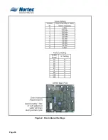
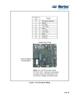
Page 63: ...Page 58 Figure 3 Control Signal Setting ...
Page 65: ...Page 60 THIS PAGE INTENTIONALLY LEFT BLANK ...
Page 66: ...Page 10 30 MAINTENANCE PROCEDURES ...
Page 69: ...Page 6 Figure 1 Minor Maintenance with Scale Management Option ...
Page 72: ...Page 6 10 40 TROUBLESHOOTING ...
Page 75: ...Page Figure 1 Wiring Diagram ...
Page 76: ...Page Figure 2 Wiring Diagram ...
Page 81: ...Page 7 THIS PAGE INTENTIONALLY LEFT BLANK ...
Page 82: ...Page 7 10 50 TECHNICAL ...
Page 83: ...Page 7 Figure 1 Exploded View Plumbing ...
Page 84: ...Page 7 Table 1 Exploded View Plumbing ...
Page 85: ...Page Figure 2 Exploded View Electrical ...