


Page
WARNING
A QUALIFIED SERVICE PERSON SHOULD PREFORM ALL MAINTENANCE
ON THE HUMIDIFIER AND ANY OTHER EQUIPMENT PROVIDED BY
NORTEC THAT REQUIRES MANTENANCE.
NOTE
Instruction and details concerning the maintenance of the NORTEC equipment
must be observed and adhered to without fail. Only the maintenance
documented in this manual must be carried out.
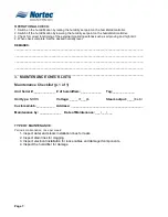
1. NHRS MAINTENANCE
A. MINOR MAINTENANCE
NOTE
The NHRS will indicate “minor maintenance due” with a yellow flashing L.E.D
and a message on the L.C.D. stating “minor maintenance due”.
(1)
Visual Inspection must be preformed before minor and major maintenance.
(a) Inspect all water and steam installations for possible leakage or damage.
(b) Inspect electrical installation for lose or frayed cables, as well as damaged
components.
(c)
Inspect the condition of the unit’s cabinetry for damage.
(d) Survey the area surrounding the humidifier make sure all clearances are met.
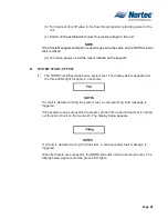
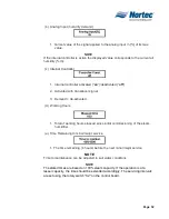
(2)
Maintenance
(a) Manually drain the NHRS by pressing the drain button on the display.
(b) Turn the units power to the off position.
(c) Switch the external electrical disconnect to the off position.
WARNING
THE NHRS HUMIDIFIER MAIN FUNCTION INVOLVES BRINGING WATER UP
TO BOILING TEMERATURES. DO NOT LOSE SIGHT OF THE FACT THAT
THE UNITS STEAM CYLINDER AND PLUMBING COMPONENTS MAY BE
HOT!!!. ALLOW THE UNIT AN APPROPRIATE AMOUNT OF TIME TO COOL
BEFORE PREFORMING SERVICE.
WARNING
HIGH VOLTAGE!!
DISCONNECT MAIN POWER BEFORE SERVICING THE UNIT.
(d) Remove the screw that holds the front door on the cabinetry in place.
(e) Remove the Front Panel by sliding the panel upward then away from the unit.
Summary of Contents for NH Series
Page 4: ......
Page 6: ...Page 1 10 00 INTRODUCTION ...
Page 7: ...Page 2 Figure 1 NHRS ...
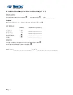
Page 11: ...Page 6 Figure 6 Typical NHRS Installation Sheet 1 of 2 ...
Page 12: ...Page 7 Figure 7 Typical NHRS Installation Sheet 2 of 2 ...
Page 13: ...Page 8 THIS PAGE INTENTIONALLY LEFT BLANK ...
Page 14: ...Page 9 10 10 INSTALLATION PROCEDURES ...
Page 17: ...Page 12 Figure 1 Plumbing Connections ...
Page 23: ...Page 18 Figure 4 Steam Run and Condensate Return Installation Guidelines 1 of 2 ...
Page 24: ...Page 19 Figure 5 Steam Run and Condensate Return Installation Guidelines 2 of 2 ...
Page 28: ...Page 23 Figure 7 On Off Guidelines and Low Voltage Terminal Strip 254 8731 ...
Page 29: ...Page 24 Figure 8 NORTEC Control Guidelines and Wiring Optional ...
Page 31: ...Page 26 Figure 10 NORTEC Humidity Transducer Guidelines and Wiring Option ...
Page 41: ...Page 36 Figure 22 Typical SAM e Duct Installation ...
Page 45: ...Page 40 Figure 25 SAM e Drain Water Cooling ...
Page 49: ...Page 44 THIS PAGE INTENTIONALLY LEFT BLANK ...
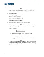
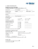
Page 50: ...Page 45 10 20 OPERATION ...
Page 60: ...Page 55 Figure 2 Drain Interval Settings ...
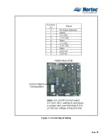
Page 63: ...Page 58 Figure 3 Control Signal Setting ...
Page 65: ...Page 60 THIS PAGE INTENTIONALLY LEFT BLANK ...
Page 66: ...Page 10 30 MAINTENANCE PROCEDURES ...
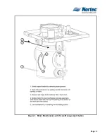
Page 69: ...Page 6 Figure 1 Minor Maintenance with Scale Management Option ...
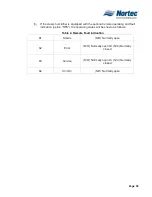
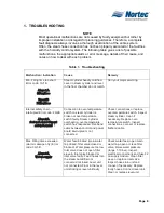
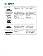
Page 72: ...Page 6 10 40 TROUBLESHOOTING ...
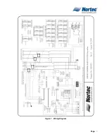
Page 75: ...Page Figure 1 Wiring Diagram ...
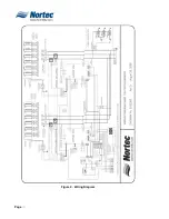
Page 76: ...Page Figure 2 Wiring Diagram ...
Page 81: ...Page 7 THIS PAGE INTENTIONALLY LEFT BLANK ...
Page 82: ...Page 7 10 50 TECHNICAL ...
Page 83: ...Page 7 Figure 1 Exploded View Plumbing ...
Page 84: ...Page 7 Table 1 Exploded View Plumbing ...
Page 85: ...Page Figure 2 Exploded View Electrical ...