10-10
Page 32
2008-10-01
3. STEAM RUNS AND CONDENSATE RETURNS
A.
STEAM RUNS
(1) Steam runs between the humidifier and the distributors can be accomplished by using
flexible NORTEC steam hose or insulated copper pipe. The longer the steam run,
including elbows, the lower the efficiency of the system. The more elbows and turns,
the higher the losses become. The humidifier should be as close as possible to the
distributor and the steam run should be as direct as possible.
(2) Guidelines for installation are:
(a) Locate humidifier as close as possible to the duct system.
(b) NORTEC steam hose should only be used on short steam runs below 10 feet.
(c) Minimize elbows and turns.
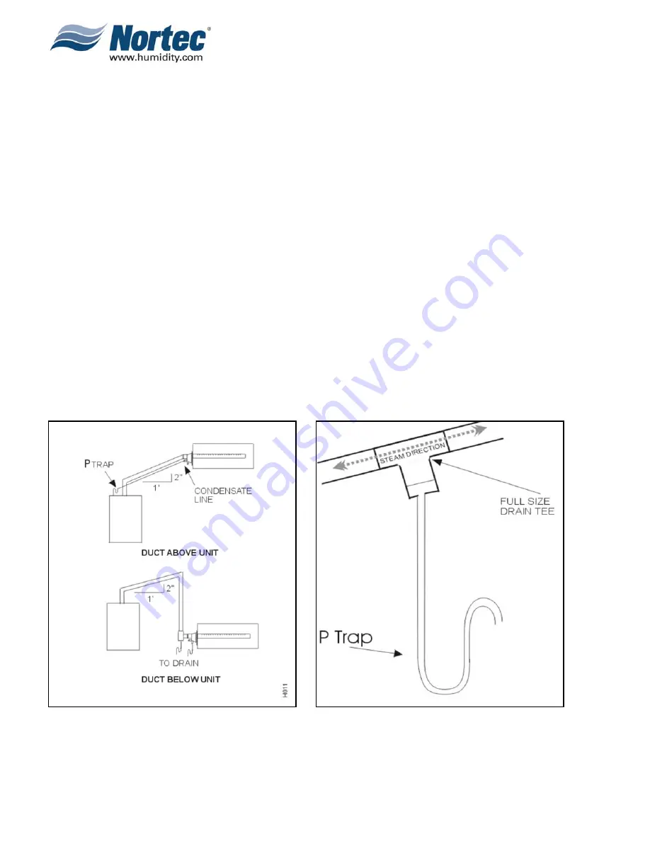
(d) Ensure that no condensate produced in the steam line will remain trapped. Steam
naturally flows upward and condensate naturally flows downward. Always slope
the steam run towards the steam source at a 15°
pitch no more (See Figure 5.).
(e) Oversize condensate line and steam line of long runs (consult your
representative).
(f)
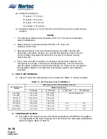
See material recommended for use in Table 11. To eliminate corrosion, NORTEC
does not recommend the use of steel piping.
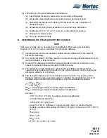
(g) Consult Table 12 and Table 13 for steam and condensate sizing guidelines when
using steam distributors.
Figure 5. Proper Slope
see Fig 9 for proper P Trap design and installation
Figure 6. Drain Tee
Summary of Contents for NHPC
Page 1: ...2538144 B NH Series NHTC NHPC ELECTRODE STEAM HUMIDIFIER Engineering Manual TM ...
Page 9: ...10 00 Page 1 2008 10 01 10 00 INTRODUCTION ...
Page 10: ...10 00 Page 2 2008 10 01 Figure 1 NHTC ...
Page 13: ...10 00 Page 5 2008 10 01 Figure 2 Optimum Boiling Time Figure 3 Conductivity ...
Page 18: ...10 00 Page 10 2008 10 01 Figure 6 Typical NHRS Installation Sheet 1 of 2 ...
Page 19: ...10 00 Page 11 2008 10 01 Figure 7 Typical NHRS Installation Sheet 2 of 2 ...
Page 20: ...10 10 Page 12 2008 10 01 10 10 HUMIDITY STEAM ABSORPTION AND DISTRIBUTION ...
Page 35: ...10 10 Page 27 2008 10 01 Figure 2 Psychrometric Chart ...
Page 64: ...10 10 Page 56 2008 10 01 Figure 30 NORTEC OnLine Monitoring ...
Page 71: ...10 20 Page 63 2008 10 01 10 20 SPECIFICATIONS ...
Page 81: ...10 30 Page 73 2008 10 01 10 30 SUBMITTALS ...
Page 86: ...10 30 Page 78 2008 10 01 Figure 2 Primary Line Voltage Wiring to Unit ...
Page 87: ...10 30 Page 79 2008 10 01 Figure 3 Physical Data NHTC NHPC 005 030 ...
Page 88: ...10 30 Page 80 2008 10 01 Figure 4 Physical Data NHTC NHPC 050 100 ...
Page 89: ...10 30 Page 81 2008 10 01 Figure 5 Physical Data NHTC NHPC 150 200 ...
Page 96: ...10 30 Page 88 2008 10 01 Figure 12 In Duct AHU Installation With Mounting Frame Installation ...
Page 98: ...10 30 Page 90 2008 10 01 Figure 13 In Duct AHU Installation With Mounting Frame Installation ...
Page 100: ...10 30 Page 92 2008 10 01 Figure 16 Atmospheric SAM e Adapter Dimensions ...
Page 101: ...10 30 Page 93 2008 10 01 Figure 17 Atmospheric Steam Header and Adapter Configuration ...
Page 102: ...10 30 Page 94 2008 10 01 Figure 18 Physical Data for Remote Mounted Blower Pack ...
Page 103: ...10 30 Page 95 2008 10 01 Figure 19 Physical Data Units with Optional Built On Blower Packs ...
Page 104: ...10 30 Page 96 2008 10 01 Figure 20 Physical Data Units with Optional Built On Blower Packs ...


