10-10
Page 38
2008-10-01
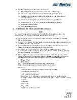
(2) Ensure the total capacity of the humidifier is not higher than the allowable maximum
steam capacity of the following distributors:
(a) ASD: 25 lbs/hr (9 kg/hr)
(b) BSD: 35 lbs/hr (13 kg/hr)
(c) CSD: 115 lbs/hr (45 kg/hr)
C.
DISTRIBUTOR LOCATIONS AND MOUNTING
(1) NORTEC distributors can be mounted in air handlers, supply air ducts or return air
ducts. Return air ducts should only be considered if all of the return air enters the
building again and is not exhausted by the air handling device. Distributors should be
mounted center or low within the duct or plenum. (See Figure 11.) Laminar airflow is
best. Down stream obstruction must be considered. The non-absorbed steam may
affect devices like smoke detectors down stream. Total steam absorption must be
accomplished before filters and silencers.
(2) Distributors come complete with a mounting plate. (See Figure 12.) Most ducts and
plenums are rigid enough to support the distributor.
(3) Longer distributors (more than 36") and distributors mounted on lighter gage sheet
metal which cannot support the distributor level in the duct will need to be supported on
the end. (See Figure 10.)
D.
MULTIPLE DISTRIBUTOR APPLICATIONS
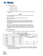
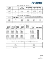
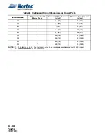
(1) The use of multiple steam distributors can reduce the absorption distance in most
situations. Distributors can be manifolded together to create a grid to achieve shorter
absorption distances. (Consult agent and/or see Nomogram Figure 13.
CAUTION
THESE INSTALLATION
GUIDELINES APPLY FOR DUCT
VELOCITIES UNDER 2000 FT/
MIN (610 M/MIN), PLEASE
CONSULT FACTORY FOR
HIGHER VELOCITIES
CAUTION
PLEASE MAKE SURE NO
OBSTACLES (ELBOW, FILTER,
OR DIFFUSER) ARE LOCATED
AFTER THE DISTRIBUTOR IN
THE DIRECTION OF THE
AIRFLOW CLOSER THAN THE
ABORPTION DISTANCE
CALCULATED FOR YOUR
APPLICATION.
CAUTION
FOR APPLICATIONS WITH
HIGH STATIC PRESSURES
PLEASE CONSULT FACTORY
Figure 11. Single Steam Distributor
Installation – Minimum Clearance
Summary of Contents for NHPC
Page 1: ...2538144 B NH Series NHTC NHPC ELECTRODE STEAM HUMIDIFIER Engineering Manual TM ...
Page 9: ...10 00 Page 1 2008 10 01 10 00 INTRODUCTION ...
Page 10: ...10 00 Page 2 2008 10 01 Figure 1 NHTC ...
Page 13: ...10 00 Page 5 2008 10 01 Figure 2 Optimum Boiling Time Figure 3 Conductivity ...
Page 18: ...10 00 Page 10 2008 10 01 Figure 6 Typical NHRS Installation Sheet 1 of 2 ...
Page 19: ...10 00 Page 11 2008 10 01 Figure 7 Typical NHRS Installation Sheet 2 of 2 ...
Page 20: ...10 10 Page 12 2008 10 01 10 10 HUMIDITY STEAM ABSORPTION AND DISTRIBUTION ...
Page 35: ...10 10 Page 27 2008 10 01 Figure 2 Psychrometric Chart ...
Page 64: ...10 10 Page 56 2008 10 01 Figure 30 NORTEC OnLine Monitoring ...
Page 71: ...10 20 Page 63 2008 10 01 10 20 SPECIFICATIONS ...
Page 81: ...10 30 Page 73 2008 10 01 10 30 SUBMITTALS ...
Page 86: ...10 30 Page 78 2008 10 01 Figure 2 Primary Line Voltage Wiring to Unit ...
Page 87: ...10 30 Page 79 2008 10 01 Figure 3 Physical Data NHTC NHPC 005 030 ...
Page 88: ...10 30 Page 80 2008 10 01 Figure 4 Physical Data NHTC NHPC 050 100 ...
Page 89: ...10 30 Page 81 2008 10 01 Figure 5 Physical Data NHTC NHPC 150 200 ...
Page 96: ...10 30 Page 88 2008 10 01 Figure 12 In Duct AHU Installation With Mounting Frame Installation ...
Page 98: ...10 30 Page 90 2008 10 01 Figure 13 In Duct AHU Installation With Mounting Frame Installation ...
Page 100: ...10 30 Page 92 2008 10 01 Figure 16 Atmospheric SAM e Adapter Dimensions ...
Page 101: ...10 30 Page 93 2008 10 01 Figure 17 Atmospheric Steam Header and Adapter Configuration ...
Page 102: ...10 30 Page 94 2008 10 01 Figure 18 Physical Data for Remote Mounted Blower Pack ...
Page 103: ...10 30 Page 95 2008 10 01 Figure 19 Physical Data Units with Optional Built On Blower Packs ...
Page 104: ...10 30 Page 96 2008 10 01 Figure 20 Physical Data Units with Optional Built On Blower Packs ...


